
Guidance
Linkage Fundamentals, the nine parts from class, then how to turn a linkage into a robot and how to document it. Keep this page open while you're in the simulator, in Onshape, and at the bench.
One motor, one circle, one footstep
Your walker gets a single TT motor. It can only spin a crank in a circle. The linkage has to turn that circle into a step: flat along the floor, then up and back for the next one.
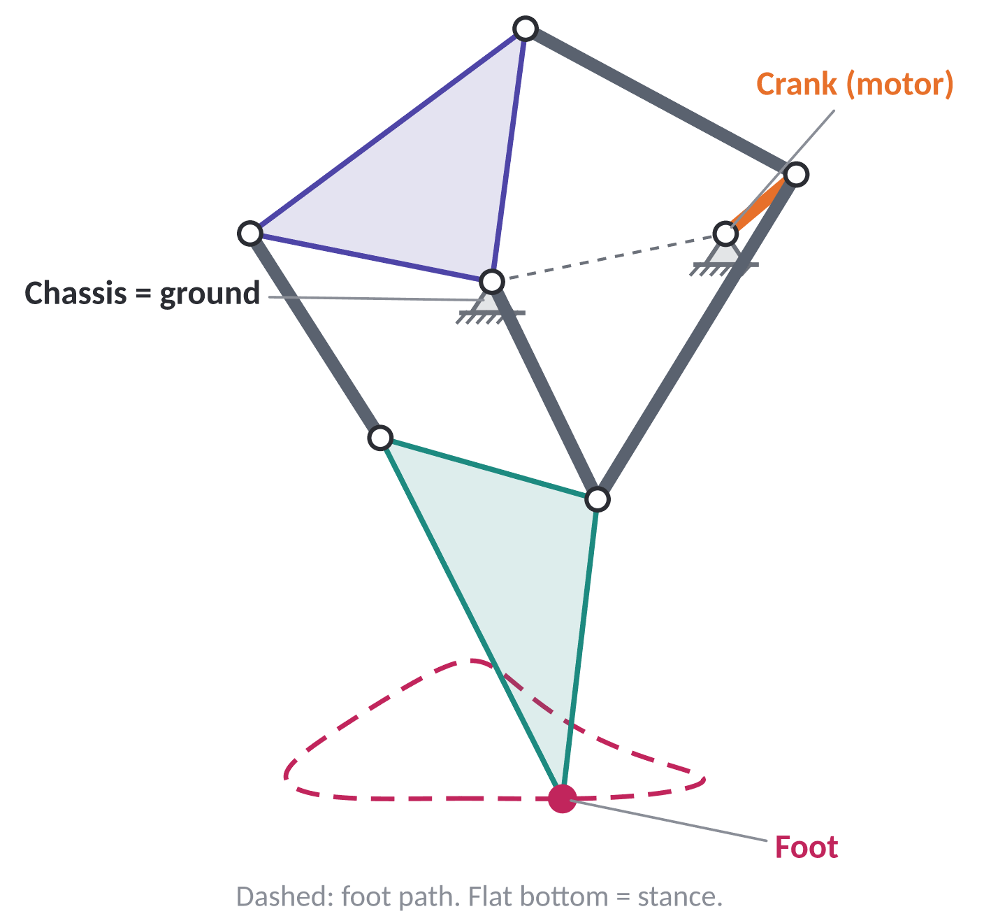
By the end of the unit you can answer nine questions about any linkage:
- Vocabulary. What are the parts called?
- Coupler curves. What paths can a linkage draw?
- Degrees of freedom. Can one motor drive it?
- Grashof condition. Will the crank turn all the way?
- Kinematic inversion. What if another link is ground?
- Transmission angle. Will the motor bog down?
- Time ratio. How long is the foot down?
- Assembly modes. Which way did it go together?
- Scaling. How big should it be?
Then: the design checks, building it, the TT motor, gears, wiring the switch, the build log, and the gallery walk.
The design process
Same six steps as every project. Steps 4 and 5 are a loop, and on this project the loop has two places to happen: the simulator first, then the wood.
- Define the problem. Read the brief. In your notebook, write the goal and every rule in your own words.
- Research and brainstorm. Look at real walkers. Sketch several leg ideas and build them in the Linkage Designer.
- Pick a solution. Run the design checks on your best ideas and compare them against the hook: distance in 15 seconds.
- Prototype. Model it in Onshape, then cut and build it. See building it.
- Test and evaluate. Run it, find what fails, fix it, and record it. See change tracking.
- Communicate. Your build log and the gallery walk.
1 · Vocabulary: links, joints, and the ground
A link is a rigid body
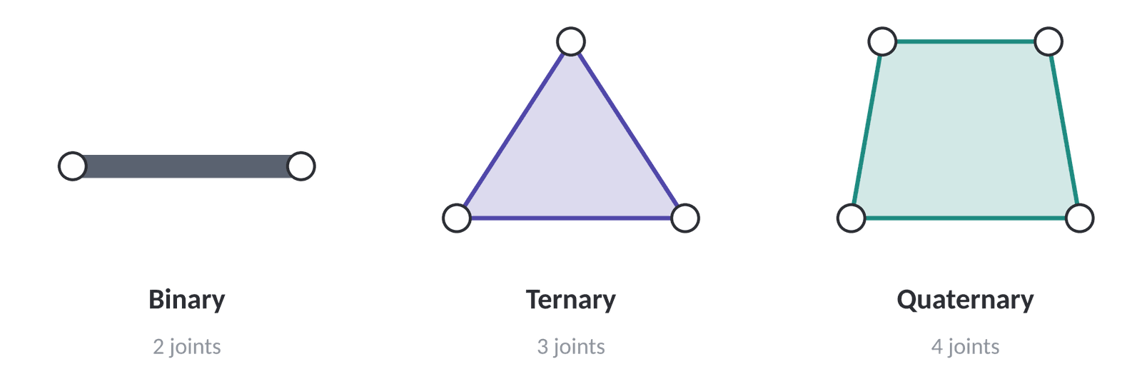
Shape doesn't matter. Joint locations do.
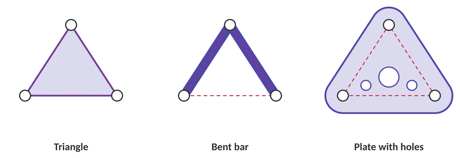
- Design freedom: bend or reshape a link to clear another part or the motor.
- Save material: lightening holes cut weight and laser time without changing the motion.
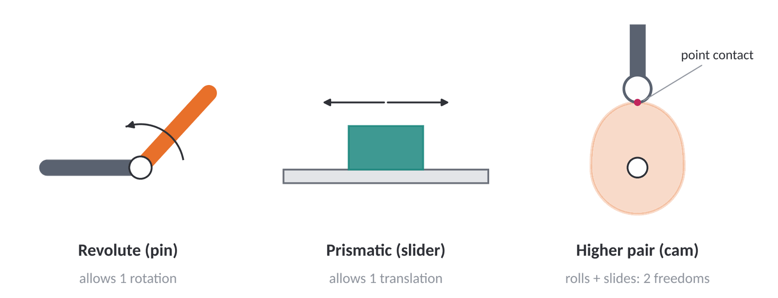
Joints connect links and allow specific motion
Ground is a link too
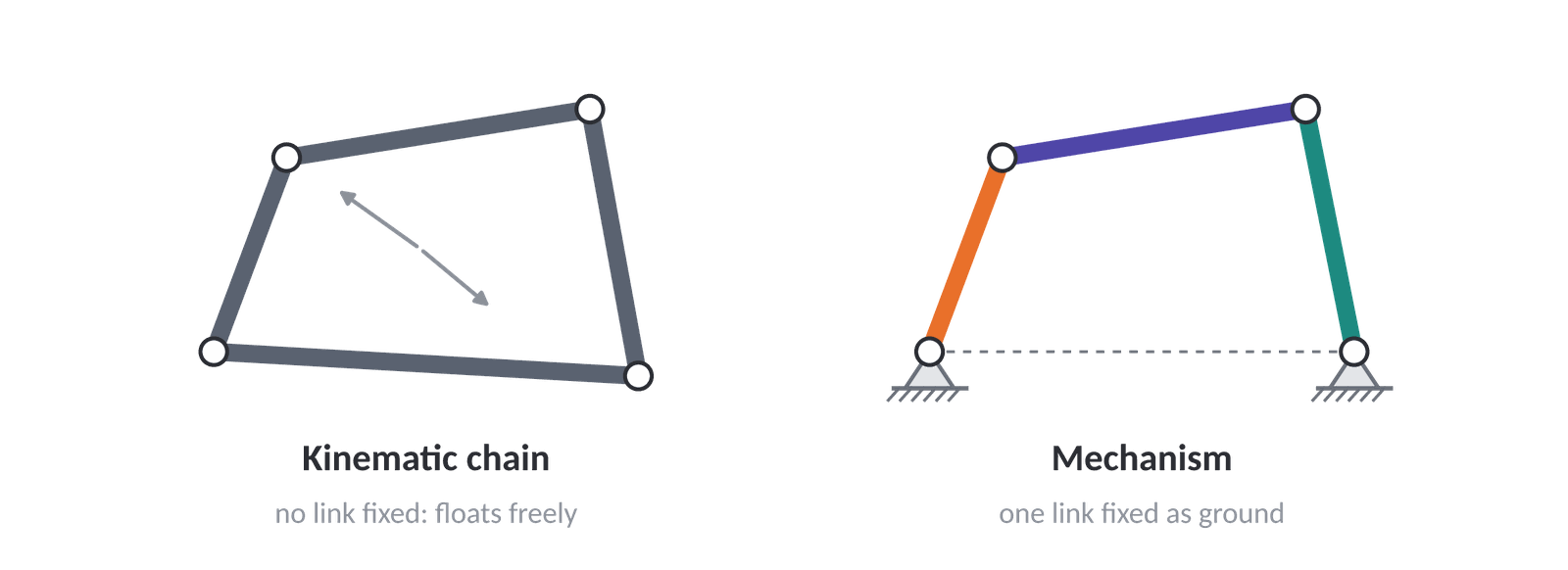
- Ground (frame) is the link that doesn't move. On your walker, it's the chassis.
- The fourth bar of a four-bar is the distance between its two fixed pivots (the dashed line). Most people count three bars. Count four.
The four-bar linkage: named roles
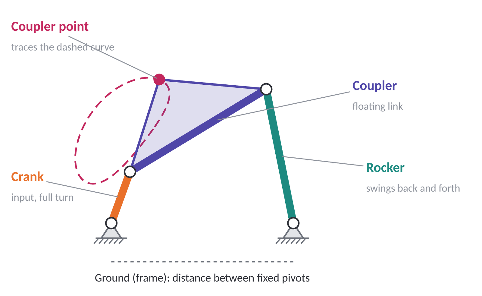
| Role | What it does |
|---|---|
| Crank | Rotates a full 360°. The motor drives it. |
| Coupler | The floating link. Never touches ground. |
| Rocker | Swings back and forth (oscillates). |
| Ground | Fixed frame between the pivots. |
Input = the driven link. Output = the link doing useful work.
Walker connection
| On every walking leg | is the |
|---|---|
| Chassis | Ground |
| Motor shaft | Crank |
| Foot | A point on a coupler, or on a link further down the chain |
A Jansen leg is just several four-bar loops chained together. Understand one four-bar and you can read any leg, one loop at a time.
Vocabulary in the MIT Linkage Designer
| In the tool | What it is |
|---|---|
| Ground node | Fixed pivot attached to the chassis |
| Simple node | Revolute joint (pin) |
| Linkage | Link (rigid bar between nodes) |
| Select motor | Marks the crank: the input link |
| Select target | The point whose path is traced (the foot) |
| DOF readout | Mobility of your mechanism (part 3) |
Try it. Build the four-bar above. Ground two nodes, link them up, select the crank as motor and a coupler point as target, then press Simulate. decode.mit.edu/links
Check: name the parts
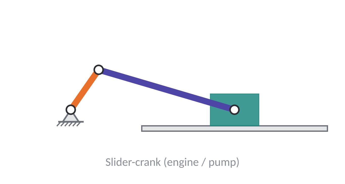
- Which link is ground?
- Which link is the crank?
- Which link is the coupler?
- What kind of joint connects the block to the rail?
- Is that joint a lower pair or a higher pair?
2 · Coupler curves: the paths a linkage can draw
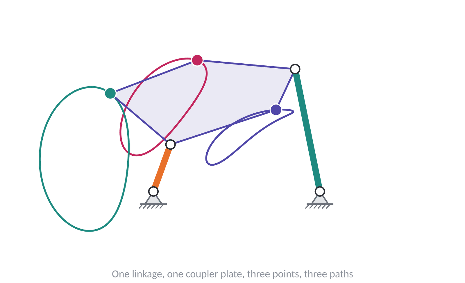
Every point traces a path
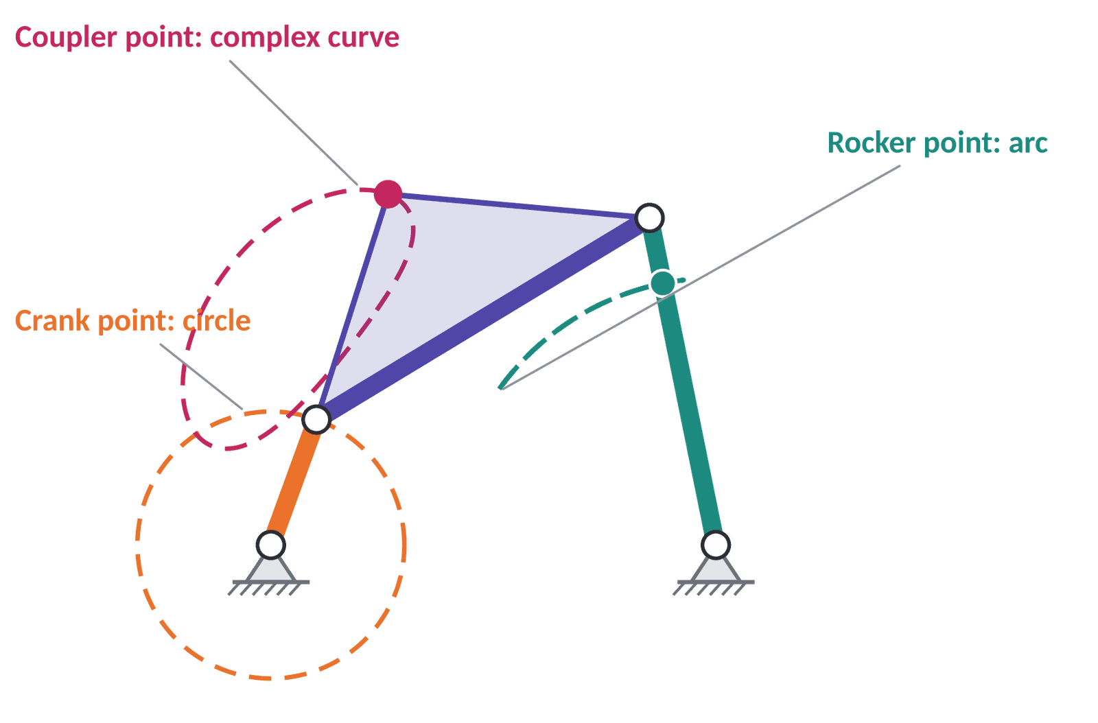
Where you put the foot changes everything
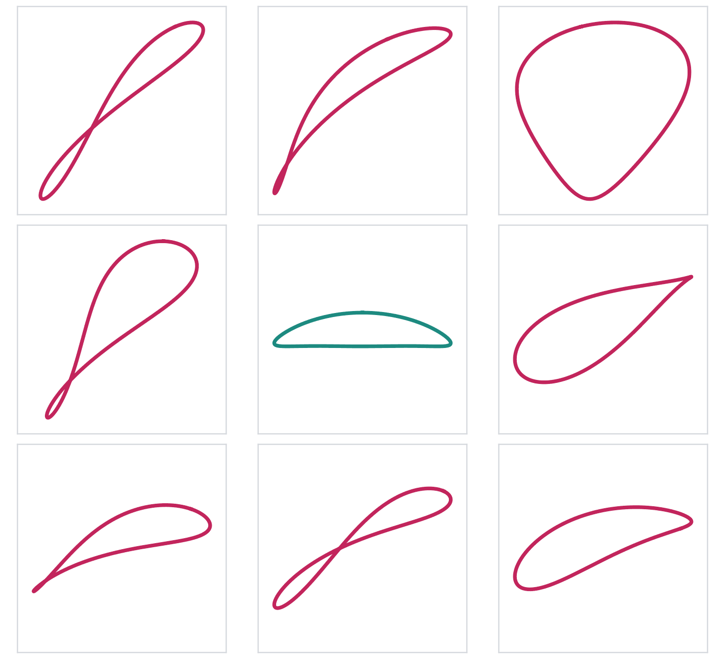
An atlas of curves
Straight-line linkages become footsteps
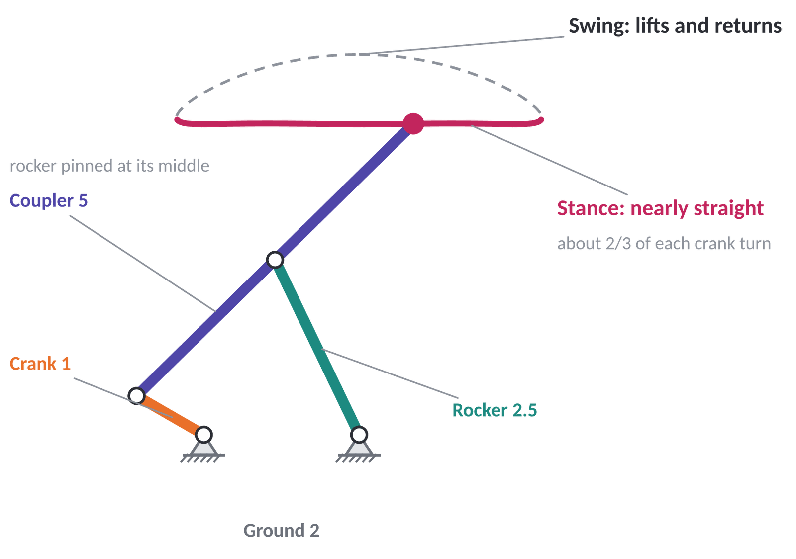
- Stance: the nearly straight edge. The foot moves level along the floor without bobbing.
- Swing: the arch. The foot lifts, clears the floor, and returns for the next step.
Chebyshev's 1878 walking machine hung its feet below a frame carried by this point, so the flat edge became the step on the floor.
3 · Degrees of freedom: can one motor drive it?
The number of independent inputs needed to fully define a mechanism's position. Count what's left after the joints, and you know how many motors it needs.
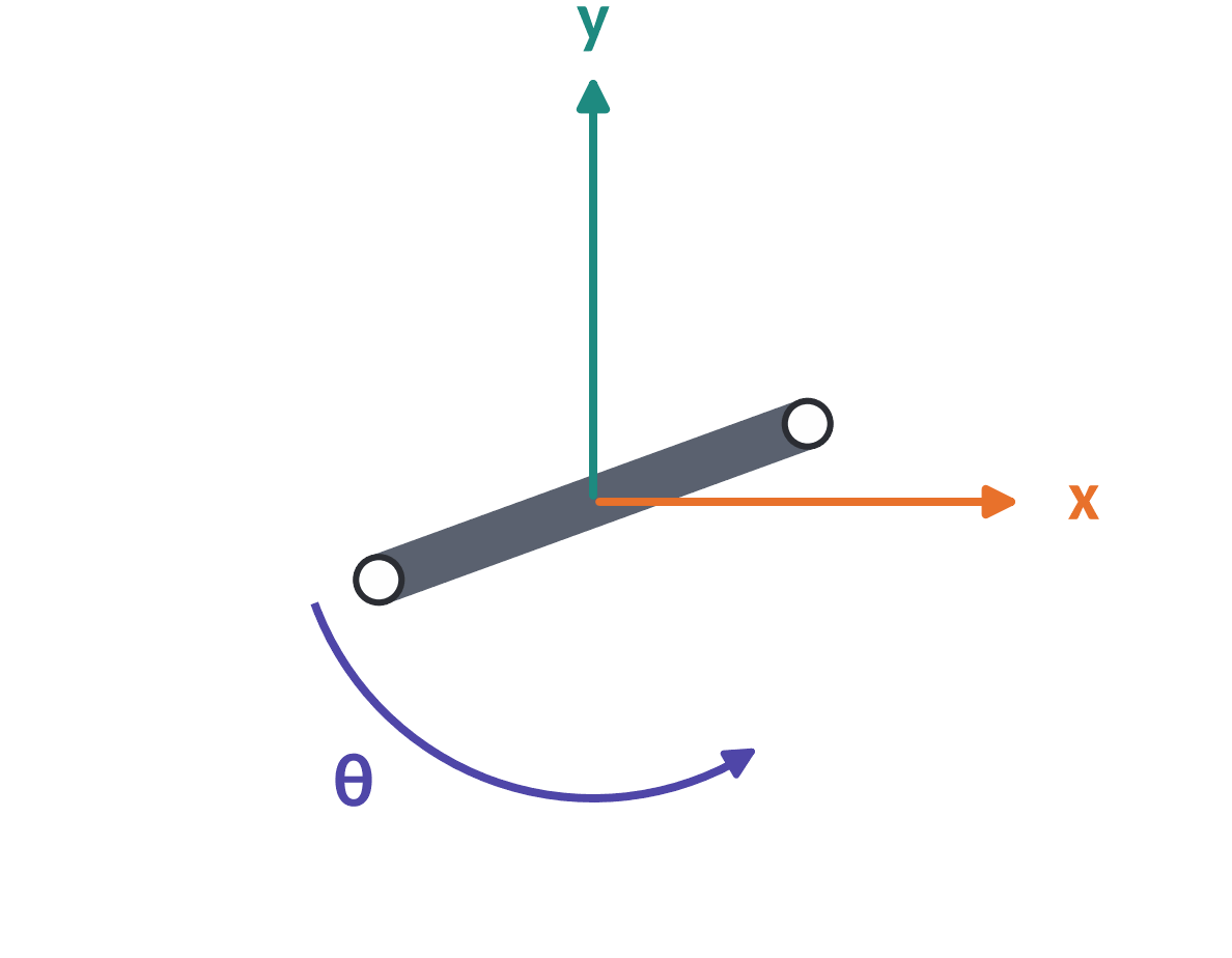
Joints remove freedom
| Joint | Allows | Removes | Counts as |
|---|---|---|---|
| Pin (revolute) | 1 | 2 | j₁ (full joint) |
| Slider (prismatic) | 1 | 2 | j₁ (full joint) |
| Cam / rolling + sliding | 2 | 1 | j₂ (half joint) |
Grübler's equation
M = 3(n − 1) − 2j₁ − j₂
M = mobility (degrees of freedom). n = number of links, including ground. j₁ = full joints (pins and sliders). j₂ = half joints (cam-type contacts).
3(n − 1): every moving link starts with 3 freedoms. Ground is fixed, so subtract it. Then each full joint removes 2 and each half joint removes 1.
Worked examples
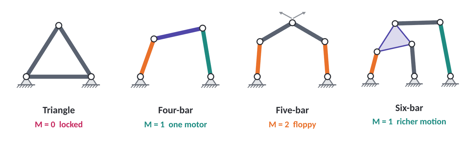
| Mechanism | n | j₁ | M | What it means |
|---|---|---|---|---|
| Triangle | 3 | 3 | 3(2) − 6 = 0 | A structure. Nothing moves. |
| Four-bar | 4 | 4 | 3(3) − 8 = 1 | One input controls it. What we want. |
| Five-bar | 5 | 5 | 3(4) − 10 = 2 | Needs two inputs. With one motor, part of it flops. |
| Six-bar | 6 | 7 | 3(5) − 14 = 1 | Back to one input, with richer motion. |
What M tells you
| M | Name | What happens |
|---|---|---|
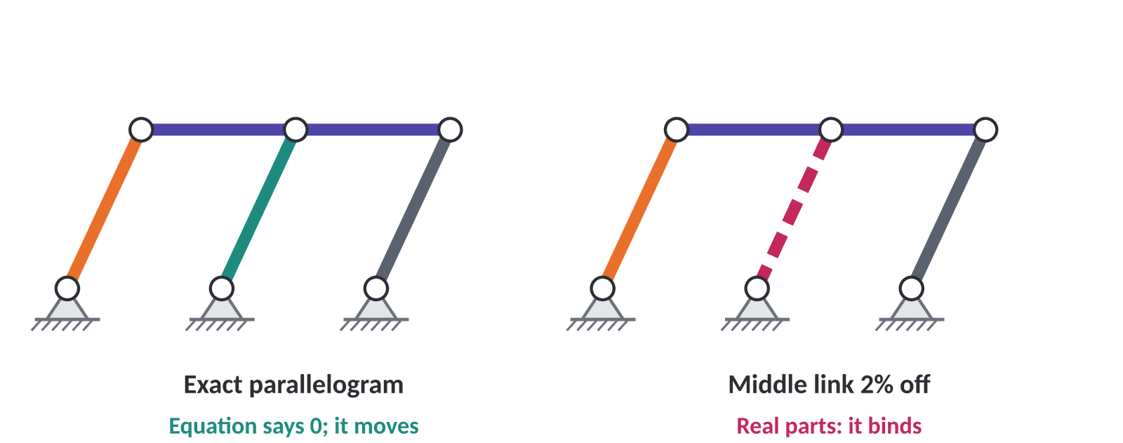
| M < 0 | Over-constrained | Statically indeterminate. Binds unless dimensions are perfect. |
| M = 0 | Structure | Nothing moves. Good for a rigid frame. The motor stalls. |
| M = 1 | Your target | One motor fully controls the mechanism. |
| M ≥ 2 | Under-constrained | With one motor, part of it hangs loose and flops. |
A single-motor walker must be M = 1. Check this before you cut a single part.
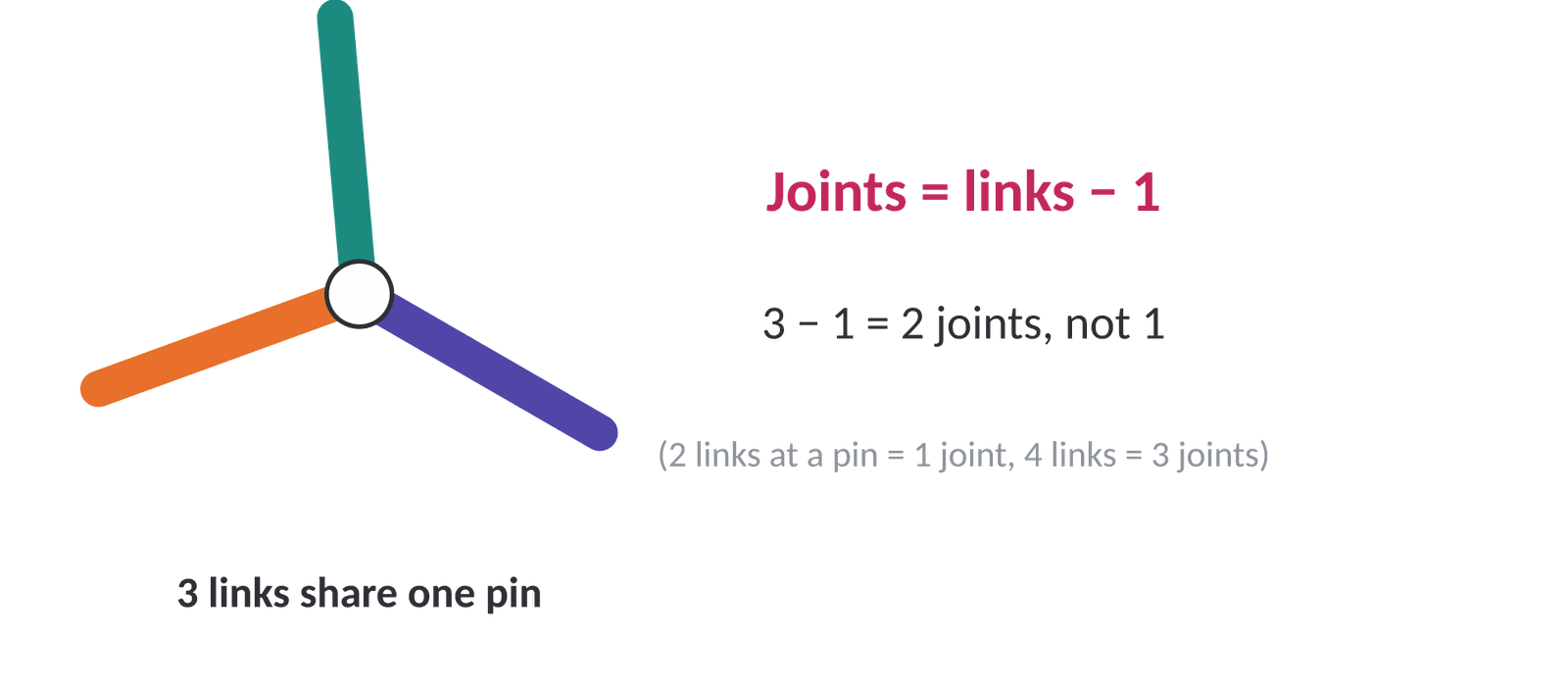
Gotcha 1: several links on one pin
Gotcha 2: the equation counts topology, not geometry
Worked example: a full Jansen leg
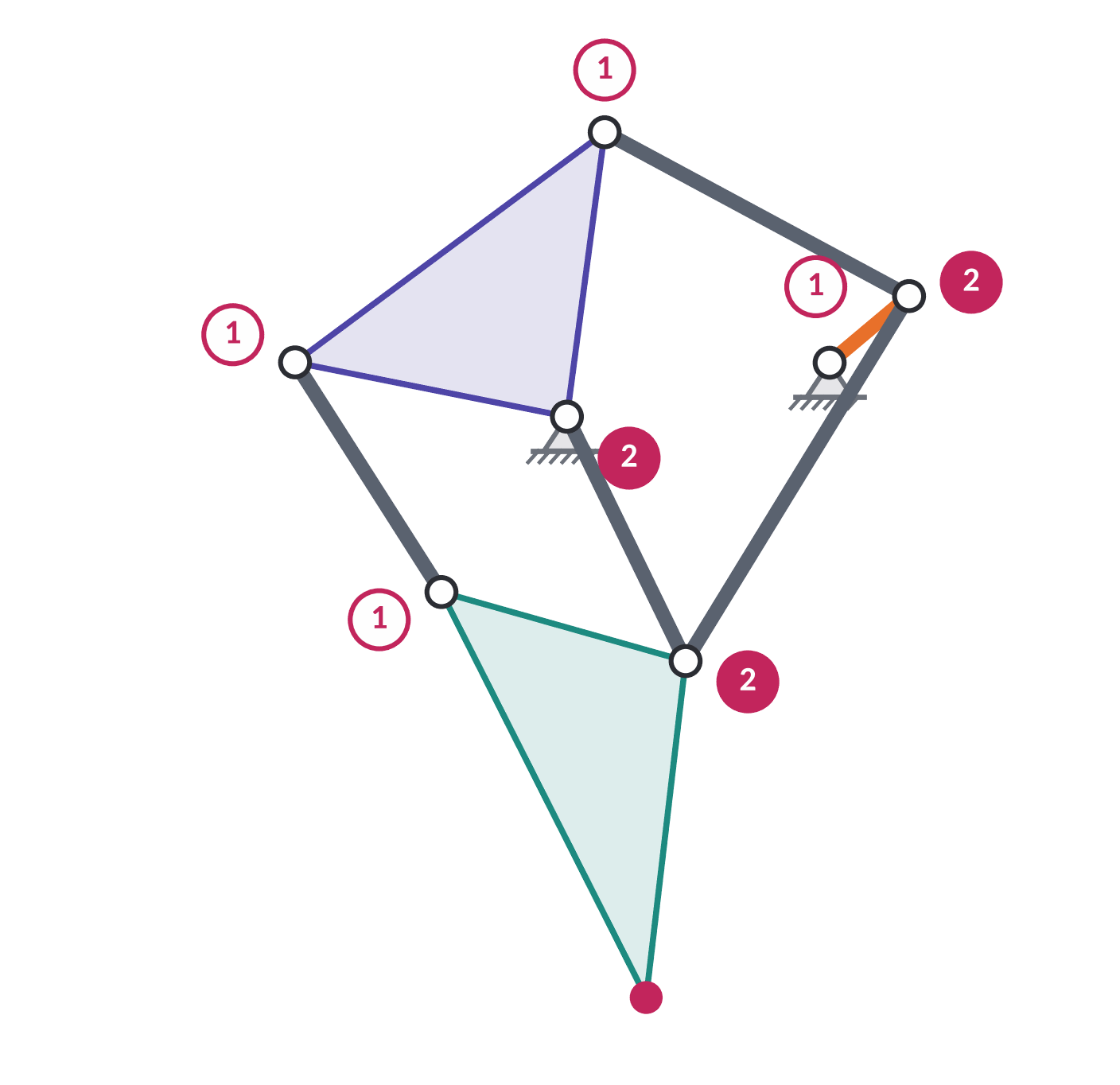
n = 8 · j₁ = 10 · M = 3(8 − 1) − 2(10) = 21 − 20 = 1
Links (8): ground, crank, 2 triangles, 4 bars. Joints (10): 1 + 2 + 2 + 1 + 2 + 1 + 1. Three pins each carry three links, so each counts as 2 joints. Miss that and you get M = 7.
More legs, same motor
Add a second Jansen leg to the same crank and the same frame:
Each extra leg shares the crank and the frame, so its links and joints cancel out. The whole robot stays at M = 1, which is exactly why one TT motor can drive every leg.
In the simulator: check the DOF counter
- Sketch a linkage on paper and compute M by hand.
- Build it in the Linkage Designer.
- Compare your M with the DOF readout. If they disagree, recount.
- Now build a linkage with DOF = 0 on purpose. Try to simulate it.
- Then build one with DOF = 2. What happens when you drive it?
Notebook. Record each linkage's n, j₁ and M, and a screenshot of the DOF readout. Note any case where your count and the tool disagreed, and why.
Practice: find M
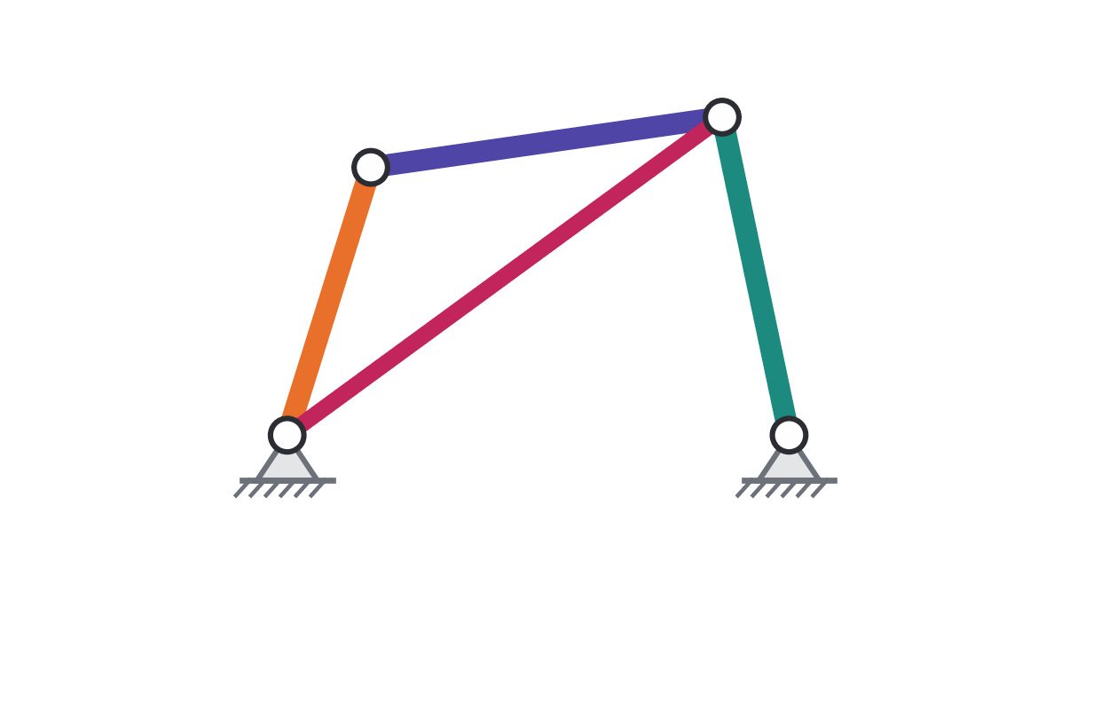
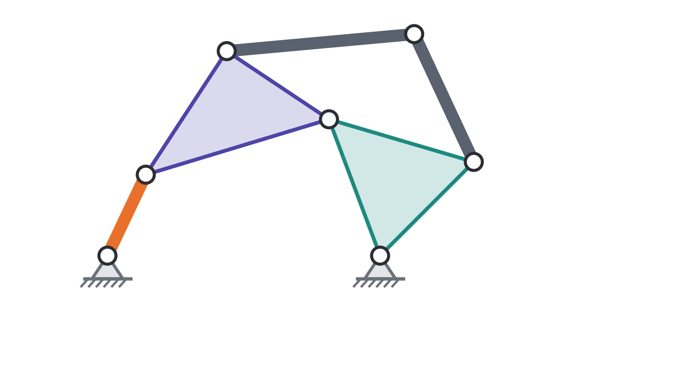
For each one: count n (include ground), count j₁ (watch shared pins), then compute M. We go over the answers in class.
4 · The Grashof condition: will the crank turn all the way?
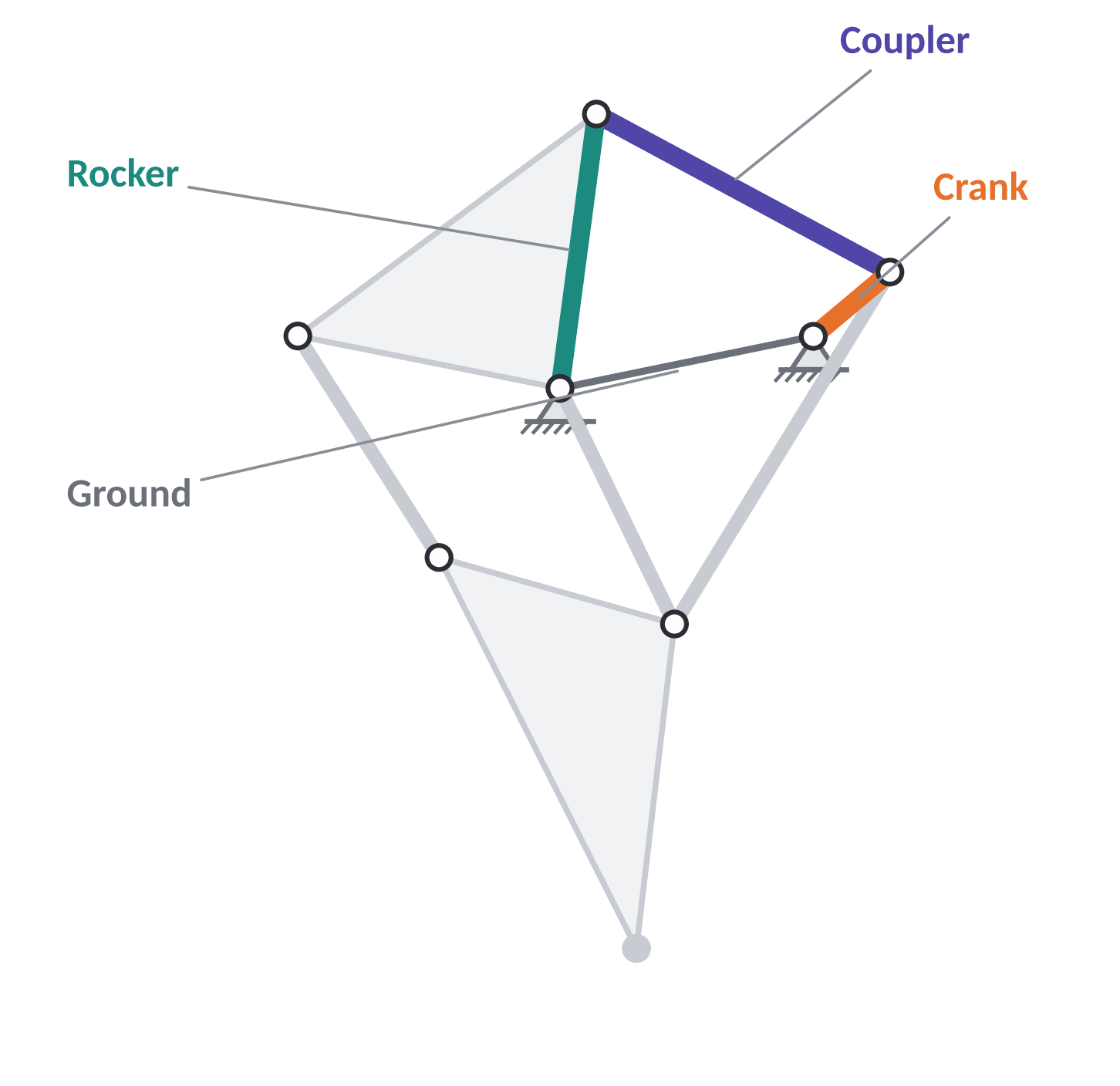
First question for every loop: can the crank turn a full 360°? A motor spins forever, so it has to.
s + l < p + q
s = shortest link. l = longest link. p and q = the other two. Count all four links, including ground.
Three possible outcomes
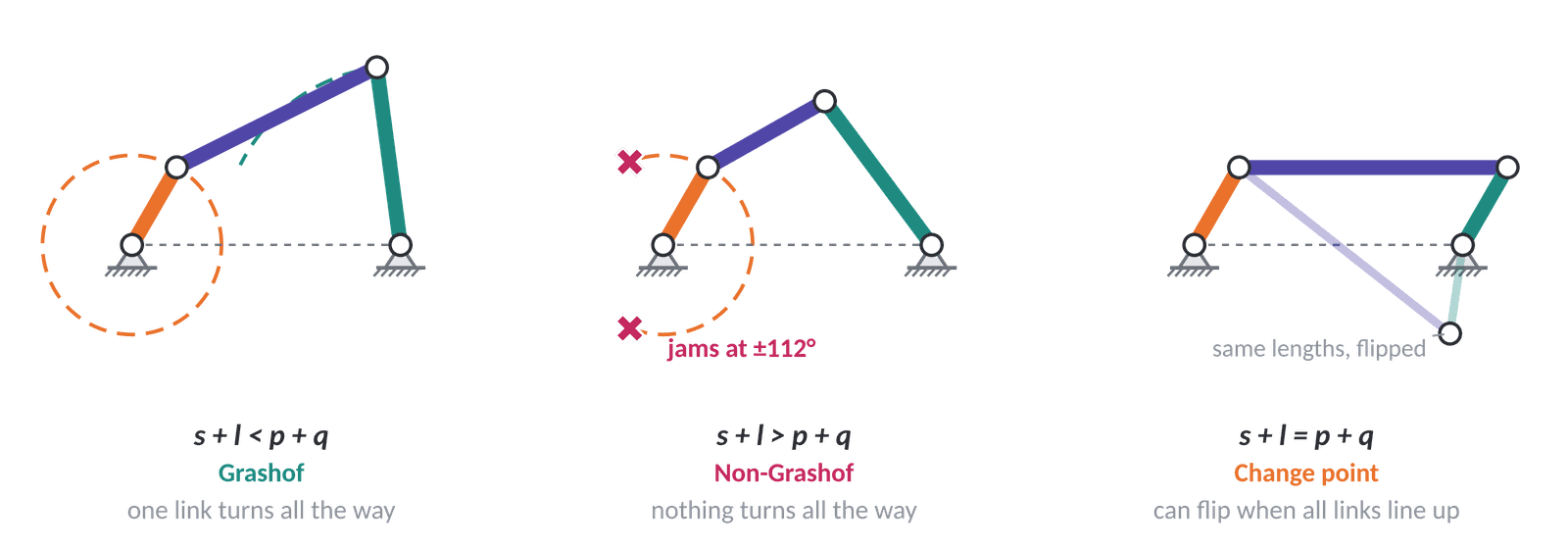
Which link is shortest?
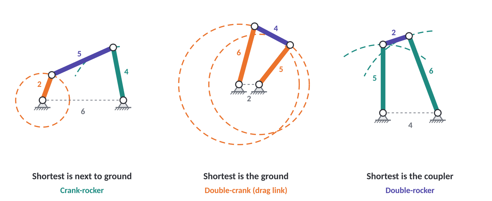
| The shortest link is… | Type | Motor on a fixed pivot? |
|---|---|---|
| Next to ground | Crank-rocker | Yes, on the shortest link |
| The ground | Double-crank (drag link) | Yes, both side links turn fully |
| The coupler | Double-rocker | No. Neither link on the ground turns all the way. |
Worked example
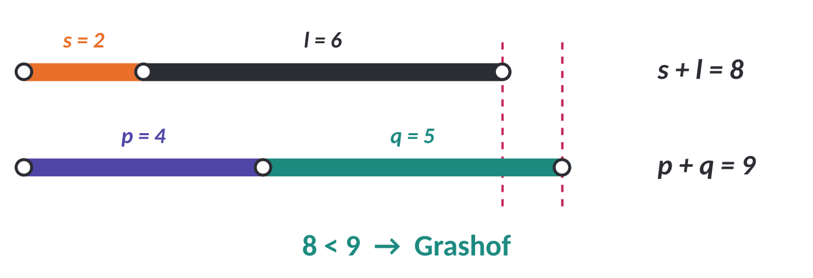
A: ground 6, crank 2, coupler 5, rocker 4
- Sort: 2, 4, 5, 6. So s = 2 and l = 6.
- s + l = 2 + 6 = 8
- p + q = 4 + 5 = 9
- 8 < 9 → Grashof
- Shortest is the crank, next to ground → crank-rocker ✓
B: shorten the coupler to 3
- Sort: 2, 3, 4, 6. So s = 2 and l = 6.
- s + l = 2 + 6 = 8
- p + q = 3 + 4 = 7
- 8 > 7 → non-Grashof
- Nothing turns all the way. A motor on the crank jams.
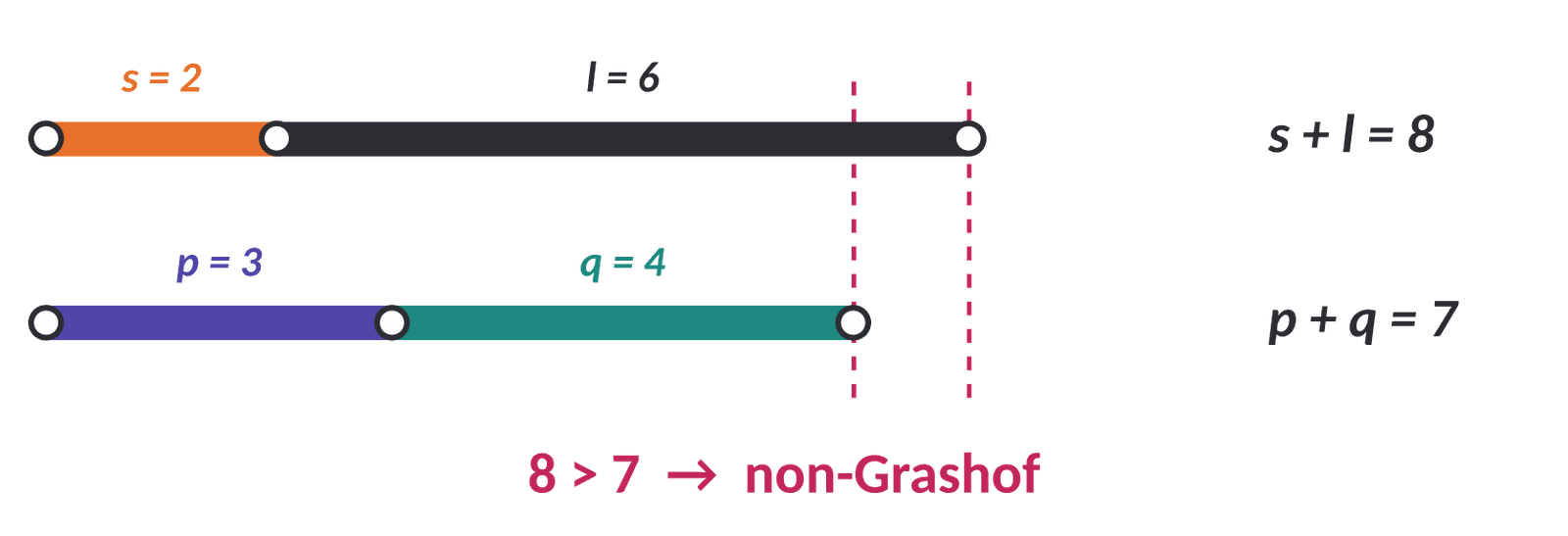
Changing one link by 2 units flips the answer. Build both in the simulator: A spins freely, and B's crank stops partway.
Check a real leg: Jansen's crank loop
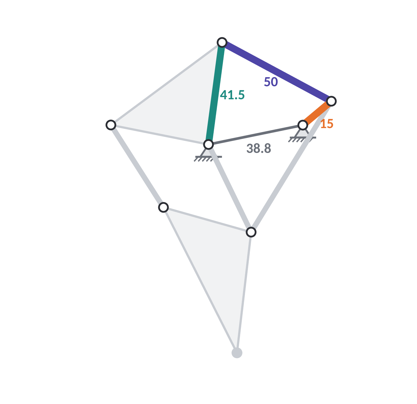
| Ground | distance between the fixed pivots | √(38² + 7.8²) = 38.8 |
| s + l | crank + coupler | 15 + 50 = 65 |
| p + q | rocker + ground | 41.5 + 38.8 = 80.3 |
| Result | 65 < 80.3 → Grashof. The crank (15) is the shortest link and sits on a fixed pivot: a crank-rocker. ✓ | |
Practice: classify each linkage
| Ground | Side 1 | Coupler | Side 2 | s + l | p + q | Type | |
|---|---|---|---|---|---|---|---|
| A | 7 | 2 | 6 | 5 | |||
| B | 3 | 7 | 8 | 6 | |||
| C | 7 | 5 | 2 | 6 | |||
| D | 5 | 3 | 4 | 7 | |||
| E | 6 | 2 | 6 | 2 | |||
| F | 6 | 4 | 5 | 2 |
Side 1 and side 2 are the two links pinned to the ground. Type: crank-rocker, double-crank, double-rocker, non-Grashof, or change point. Bonus: for each crank-rocker, which side gets the motor? We go over the answers in class.
Rule for your walker
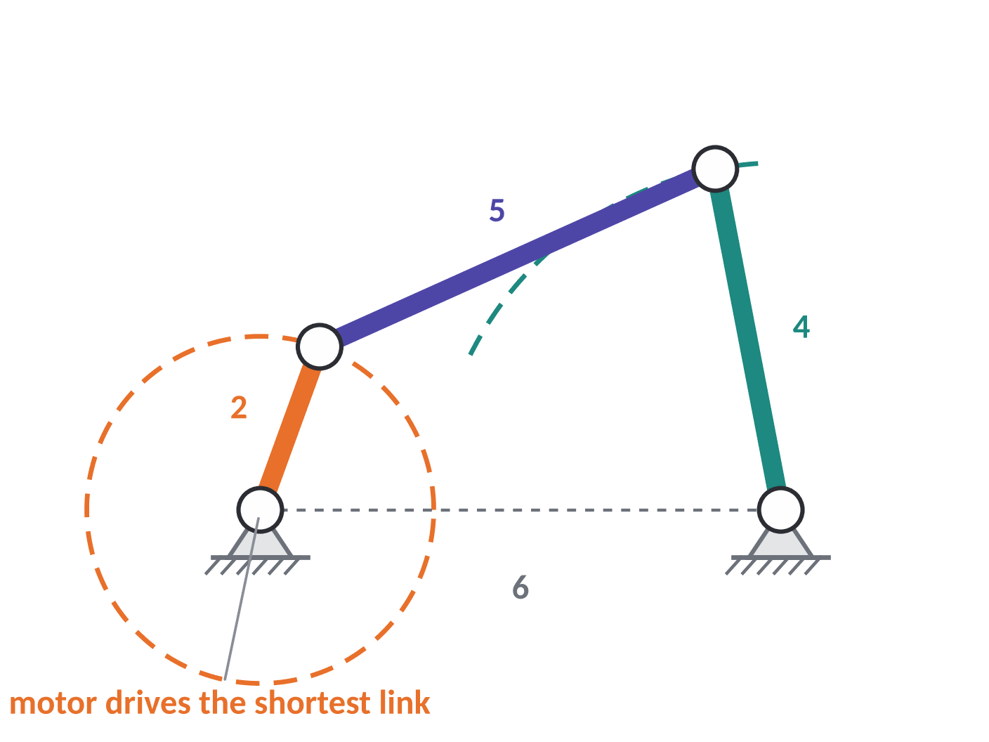
- Every loop that contains the crank passes Grashof: s + l < p + q (not equal).
- The crank must be the shortest link in its loop, or the ground must be.
- Most walkers use a crank-rocker: the motor turns the shortest link, which is pinned to the chassis.
In the simulator: if your crank stops partway or snaps to a new shape, check Grashof first.
In the Design Lab: the Four-Bar Analyzer runs the Grashof test on your four lengths, names the type, and marks where the crank jams.
5 · Kinematic inversion: same links, different ground
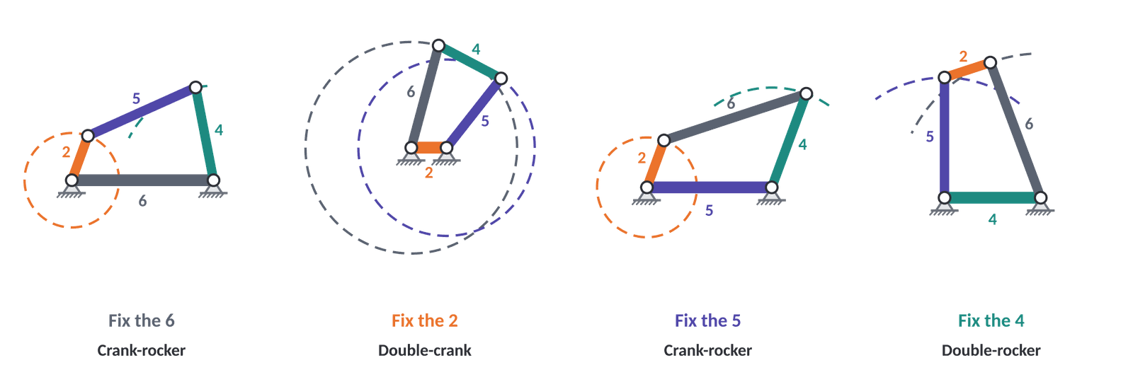
Why the Grashof table works
In a Grashof chain, the shortest link can turn all the way around relative to every other link.
| Fix… | What happens | Type |
|---|---|---|
| A neighbor of the shortest (the 6 or the 5) | The shortest spins around a fixed pivot. | Crank-rocker |
| The shortest (the 2) | Both neighbors spin around it. | Double-crank |
| The link across from it (the 4) | The shortest still spins, but it isn't on the ground. | Double-rocker |
Try it: four inversions in the simulator
- Build the 6-2-5-4 chain with the 6 as ground and the motor on the 2.
- Rebuild with the 2 as ground, then the 5, then the 4.
- Each time, put the motor on a link touching the ground and simulate.
- Record which links turn all the way and which only rock.
Notebook. Copy this table: Ground · Turns fully · Rocks · Type, with a row for each of 6, 2, 5 and 4. Add a screenshot of each inversion and circle the link the motor drives.
6 · Transmission angle: why a linkage can look great and still stall
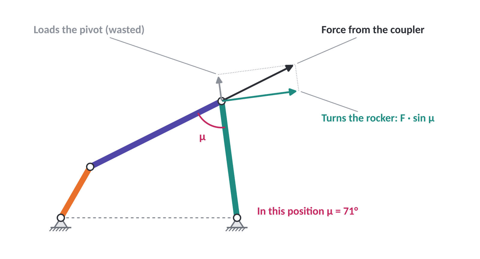
| Definition | μ is the angle between the coupler and the rocker. |
| Near 90° | Most of the coupler's force turns the rocker. |
| Near 0° or 180° | The force mostly squeezes the joints. Friction rises and the motor bogs down. |
Keep μ between 40° and 140° all the way around.
Same Grashof test, very different μ
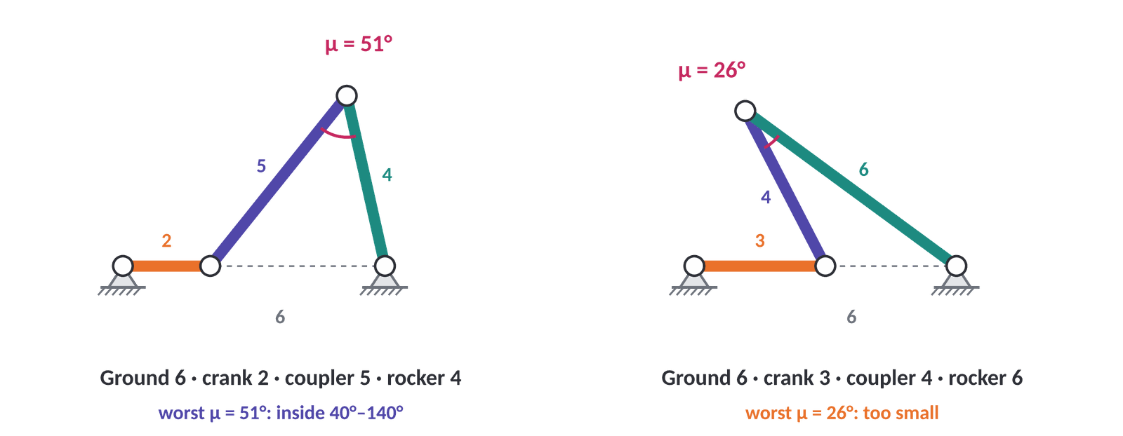
μ all the way around
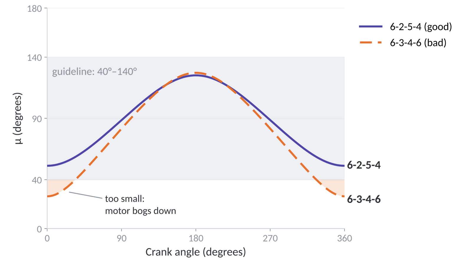
- Worst positions: μ is smallest and largest when the crank lines up with the ground, at 0° and 180°.
- Shortcut: you don't need the whole graph. Check those two positions.
Worked example: find the worst μ
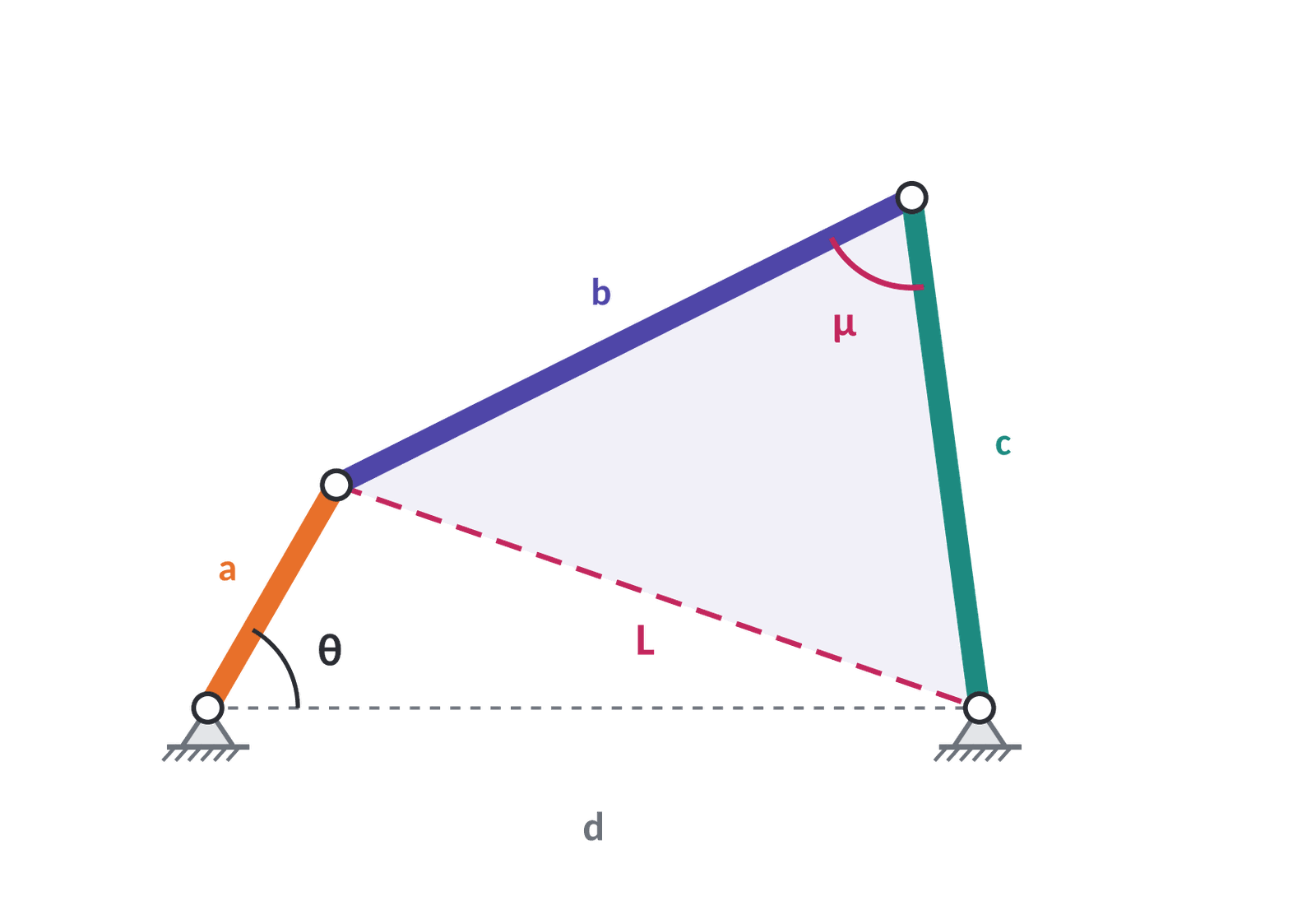
cos μ = (b² + c² − L²) ÷ (2bc)
L is the diagonal from the crank tip to the rocker pivot. At 0°, L = d − a. At 180°, L = d + a. Calculator in degree mode.
| Crank at 0° | Crank at 180° | |
|---|---|---|
| L | 6 − 2 = 4 | 6 + 2 = 8 |
| cos μ | (25 + 16 − 16) ÷ 40 = 0.625 | (25 + 16 − 64) ÷ 40 = −0.575 |
| μ | 51.3° | 125.1° |
51° to 125°: inside 40°–140° ✓. Your turn: ground 6, crank 3, coupler 4, rocker 6.
Toggle positions
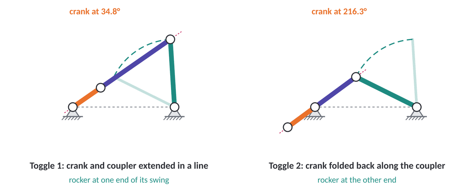
- Motor drives the crank: the rocker just reverses at each toggle. No problem.
- If the rocker drove: crank and coupler line up, so pushing can't turn the crank. It locks. That's why the motor always drives the crank, and why a hand-turned prototype can catch at the same spot every turn.
In the Design Lab: the Four-Bar Analyzer plots μ all the way around the turn, shows the two toggle positions, and tells you how many degrees fall outside 40° to 140°.
7 · Time ratio: slow stroke, quick return
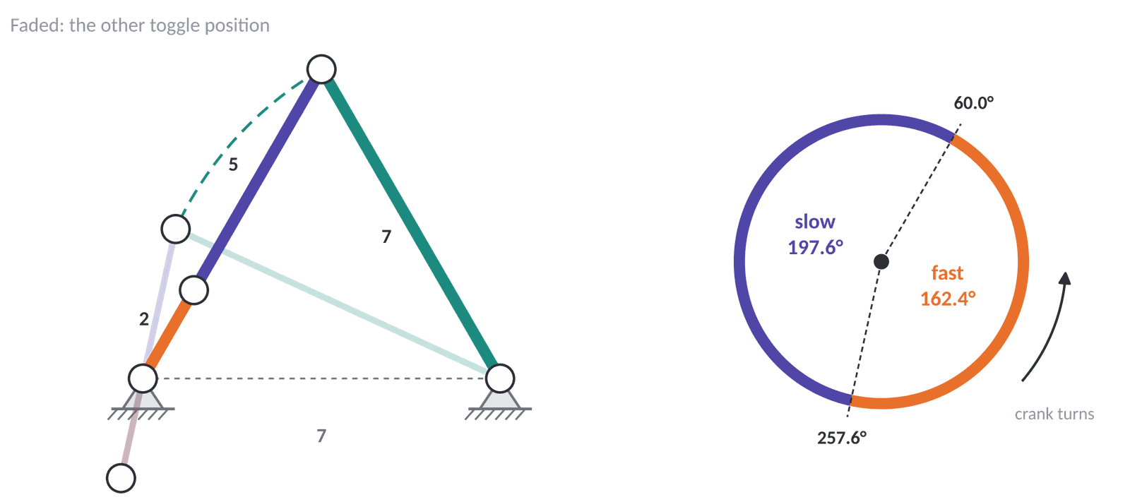
Q = slow angle ÷ fast angle = 197.6° ÷ 162.4° = 1.22
Reverse the motor and the slow swing goes the other direction.
Worked example: find Q
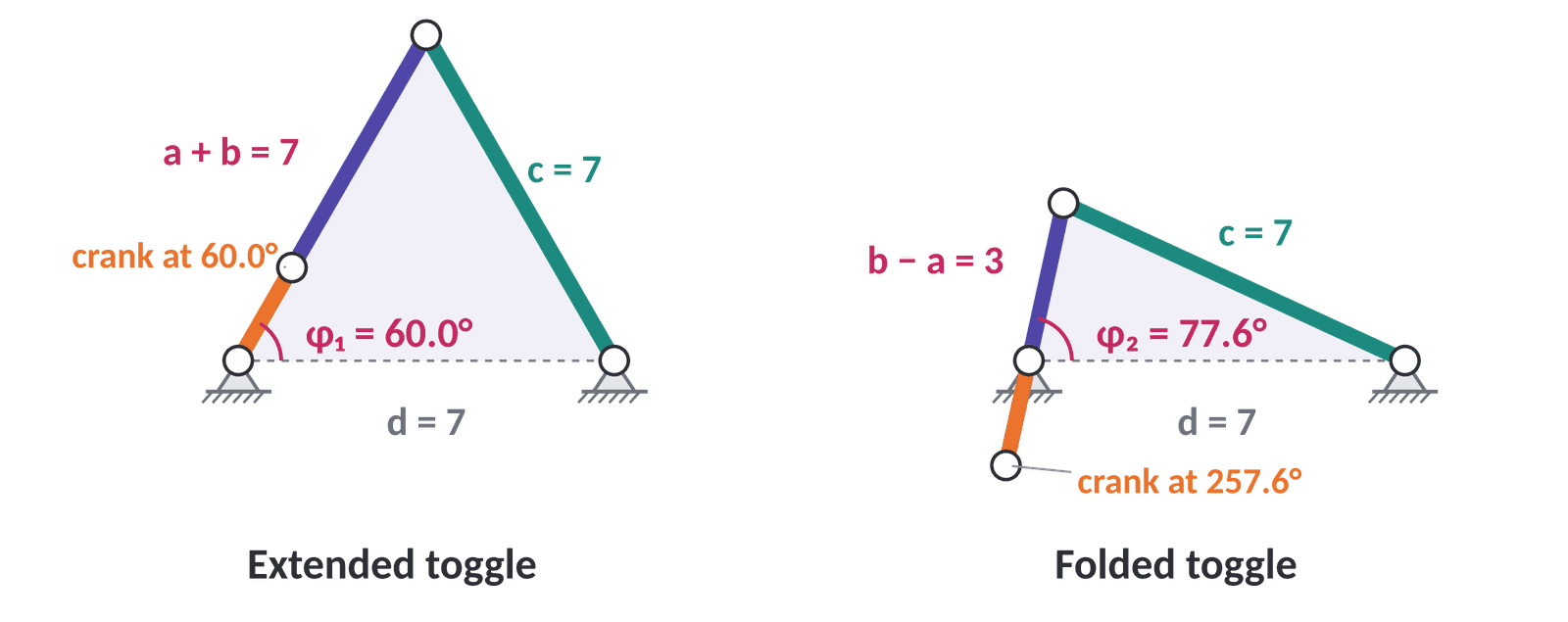
cos φ = (d² + side² − c²) ÷ (2 · d · side)
side = a + b when extended, b − a when folded.
- Extended: side = 7. cos φ₁ = (49 + 49 − 49) ÷ 98 = 0.5, so φ₁ = 60.0°
- Folded: side = 3. cos φ₂ = (49 + 9 − 49) ÷ 42 = 0.214, so φ₂ = 77.6°
- The folded crank points the other way: 77.6° + 180° = 257.6°
- Slow = 257.6° − 60.0° = 197.6°. Fast = 360° − 197.6° = 162.4°
- Q = 197.6 ÷ 162.4 = 1.22
Compare: the 6-2-5-4 linkage has Q = 1.02, almost even.
Walker connection: duty factor
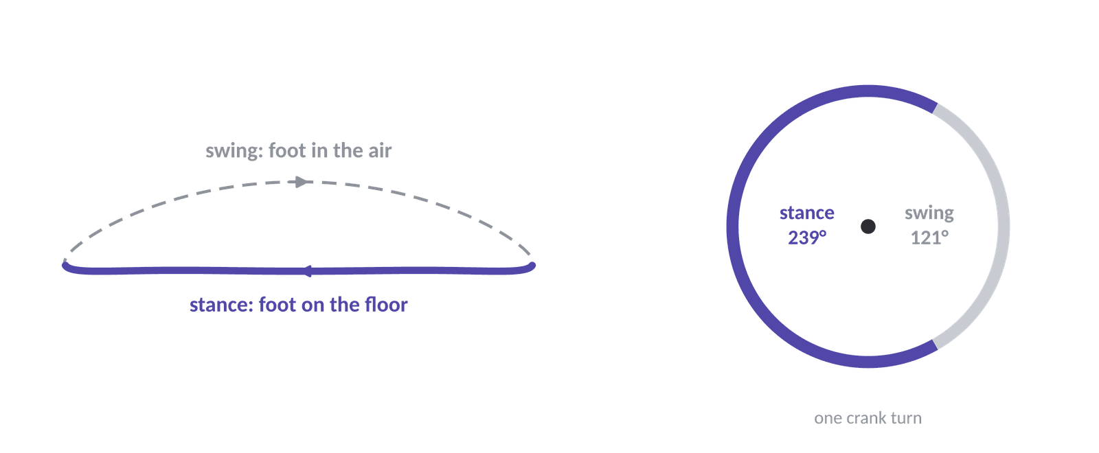
duty factor = stance angle ÷ 360° = 239° ÷ 360° ≈ 0.66
The Chebyshev foot is on the floor for about two thirds of every crank turn.
Why stance should be more than half
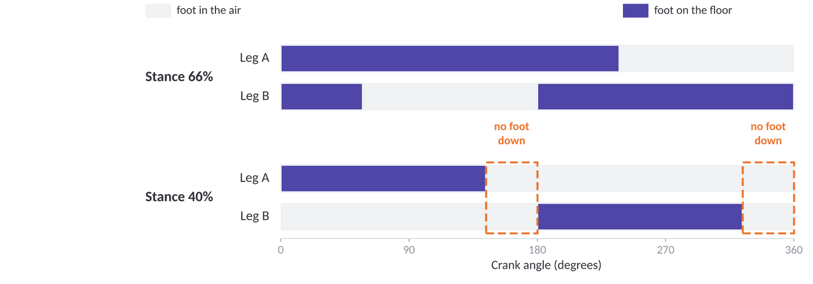
- Stance over 50%: with two legs 180° apart, at least one foot is always down.
- Stance under 50%: there are moments with no foot down. The body drops or drags. This is also why Jansen uses three legs per side, 120° apart.
In the Design Lab: Leg and Foot Path finds your leg's stance angle and duty factor, and tells you whether a foot is always down. It splits the foot path a little differently from the slide, so it gives 248° for the Chebyshev leg, not 239°. Either is fine.
8 · Assembly modes: two ways to put the same links together
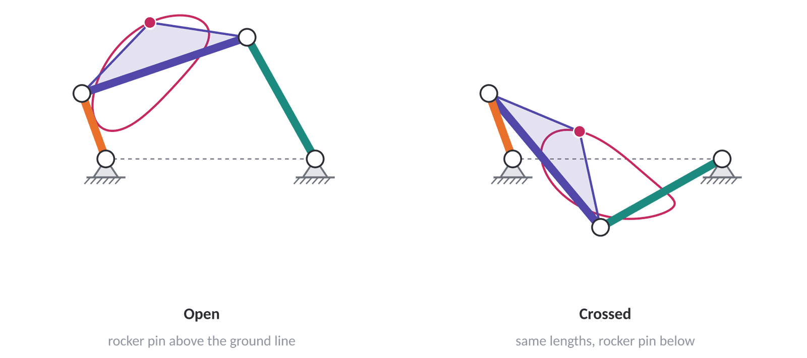
- Same lengths: same crank angle, different shape and foot path.
- Can't switch: you'd have to take it apart to change modes. It only happens if parts get pinned together the wrong way.
- Check it: compare your build to your drawing before you blame the design.
In the simulator, editing a length can make the solver pick the other mode. It looks like the linkage suddenly flipped.
9 · Scaling: bigger stride, bigger load
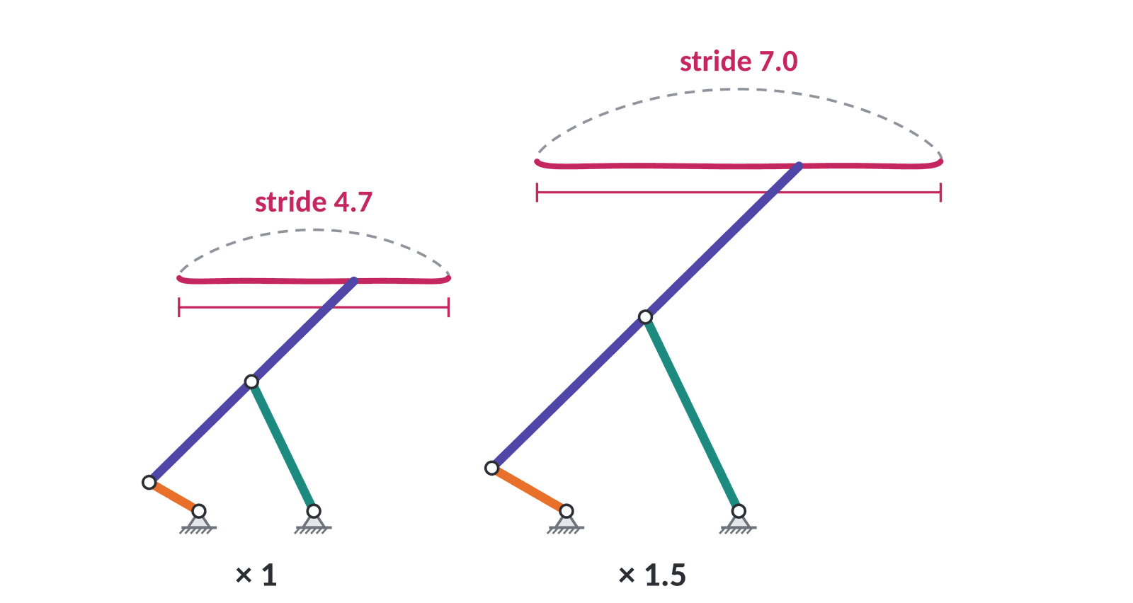
Design move: find the shape you like in the simulator first, then scale it to the stride you want.
The trade-off
| Scale every link by k, and… | changes by |
|---|---|
| Stride | × k |
| Foot speed at the same crank speed | × k |
| Motor torque for the same load | × k |
| Weight | heavier: longer links weigh more |
speed ≈ stride × crank turns per second
Each crank turn moves the robot about one stride, as long as the feet don't slip. Multiply by 15 for your distance.
| Speed | In 15 s | |
|---|---|---|
| Original | 4 cm × 1.5 turns/s = 6 cm/s | 90 cm |
| Scaled 1.5×, motor slows a little | 6 cm × 1.2 turns/s = 7.2 cm/s | 108 cm |
| Scaled 1.5×, motor slows a lot | 6 cm × 0.9 turns/s = 5.4 cm/s | 81 cm |
A closer estimate. One stride per turn is right for a single leg. With two or more legs sharing the work, a foot is always pushing, so each turn moves the robot about stride ÷ duty factor. That's more than one stride. Motor and Speed in the Design Lab works it out for your leg and your motor.
Made-up crank speeds — you'll measure real ones in the Motor Lab. See the TT motor for the datasheet numbers. A TT motor slows down as its load goes up. A bigger walker is only faster if the motor doesn't slow down by more than the stride grows.
The design checks
Run every one on paper or in the simulator before you cut a single part. Show the work in your notebook. These are what Research and Brainstorm is scored on.
- M = 1. Count ground, and count shared pins as (links − 1) joints. Part 3.
- Grashof on every loop that contains the crank: s + l < p + q, not equal. Part 4.
- The motor drives the shortest link in its loop (or the ground is shortest). Part 4.
- Worst transmission angle between 40° and 140°. Check the crank at 0° and 180°. Part 6.
- Stance more than half a turn, or legs phased so a foot is always down. Part 7.
- No design that only works with perfect dimensions. Kerf and hole slop will make it bind. Part 3, gotcha 2.
- Your build matches your drawing. Same assembly mode. Part 8.
- Four-Bar Analyzer: Grashof, transmission angle, toggle positions, and time ratio.
- Leg and Foot Path: stride, duty factor, body bob, and the torque it takes to lift the robot.
- Motor and Speed: the Motor Lab, then a prediction of how far your robot walks in 15 seconds.
The lab checks your math. It doesn't replace it. Your notebook still has to show every step by hand.
Building it: from the simulator to wood
- Hole centers are your link lengths. The distance between two holes on a link is the length from the simulator. Everything else about the shape is yours to change — see shape doesn't matter.
- Put link lengths in Onshape variables (for example
#crank,#coupler) and use them for every hole spacing. When a check fails, you change one number instead of redrawing the part. - Every pin is a standoff or a bolt. Threaded standoffs, or spacers with a bolt through. A moving link has to turn freely on its pin without wobbling off it. Test the fit on scrap wood before you cut every link.
- Plan the stack. Links that cross each other sit on different layers. Spacers keep them from rubbing. The crank pin usually carries two or three links — that's gotcha 1 in real life.
- The chassis is ground. The fixed pivots and the motor all mount to it, so the distance between fixed pivots on the chassis is a link length too.
- Shoes. Rubber bands, hot glue, or anything else with grip on the feet. Every slipped step is distance you don't get.
Read Making Parts before you send anything to the laser cutter or the printer.
The TT motor
The blue TT motor is two things in one: a small DC motor that spins very fast, and a 1:90 gearbox that slows it down. The output shaft turns once for every 90 turns of the motor inside. You lose speed and gain torque.
These numbers come from the manufacturer's datasheet.
| From the datasheet | Value | What it means for you |
|---|---|---|
| Gear ratio | 1:90 | Already geared down. Your own gears add to this. |
| Voltage | 3 to 6 V DC | Your 4.8 V pack is inside the range. |
| Starting voltage | 1.2 V (1.6 V max) | The least voltage that gets it turning with no load. |
| Direction | Either way | Swap the two wires to reverse it. |
| Mounting | Any position | Upright, sideways, or upside down all work. |
| No load, at 3 V | 130 rpm · 0.10 A | Its top speed at 3 V, with nothing attached. |
| Stalled, at 3 V | 0 rpm · about 1.0 A | Jammed: ten times the current, and no motion. |
turns per second = rpm ÷ 60
130 rpm ÷ 60 ≈ 2.2 turns per second. That's the number that goes into speed ≈ stride × crank turns per second.
Load slows it down
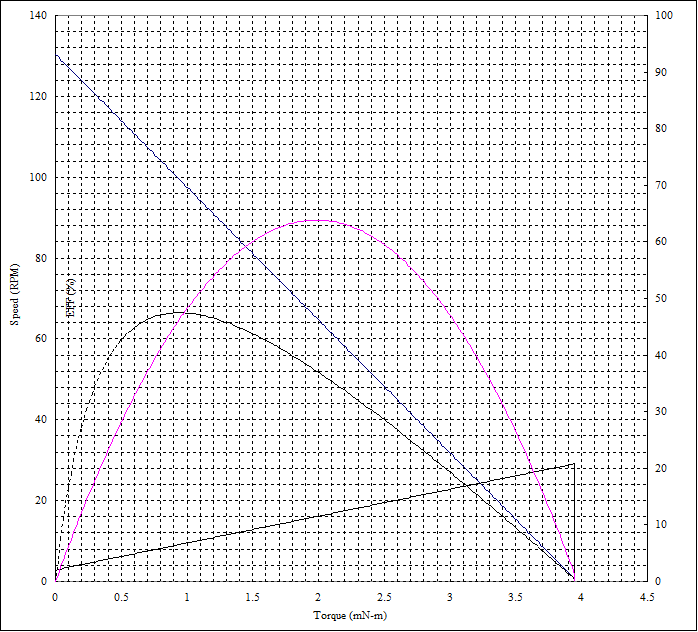
- Every bit of drag is load. Weight, binding joints, rubbing links, and a bad transmission angle all slow the crank. That's why a bigger walker is only faster if the motor doesn't slow down more than the stride grows (part 9).
- Aim for the left half of the graph, between best efficiency (99 rpm at 3 V) and most power (about 65 rpm). If your crank is crawling, you're close to stall. Cut the load (lighter links, fix binding, better μ) or add a gear reduction (below).
- Stalled is bad for everything. It pulls about ten times the no-load current, drains the batteries, and heats the motor. If the robot jams, switch it off right away.
- Your pack is 4.8 V, not 3 V, so it turns faster than these numbers. A DC motor's speed rises roughly with voltage, so expect somewhere near 200 rpm with no load, and less with legs attached. That's an estimate. Measure your real motor in the Motor Lab.
Sizes for your CAD
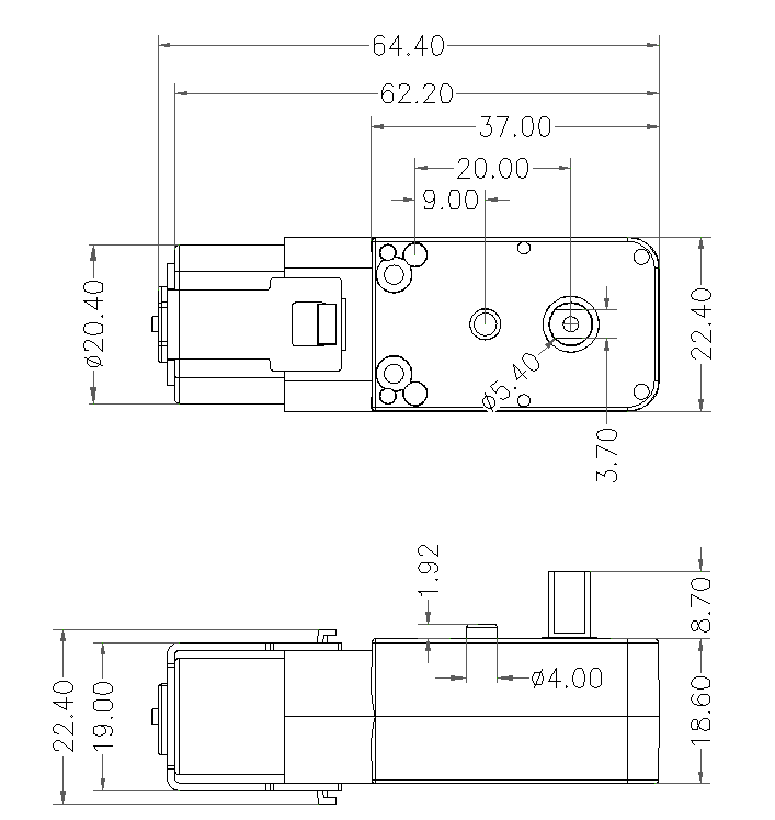
- The shaft is a double D: 5.4 mm across, with two flats 3.7 mm apart. Cut that exact shape into your crank or gear, so it grips the flats and can't spin on the shaft.
- The shaft sticks out 8.7 mm. That's all the length your crank or gear has to grab, so keep the parts on it thin.
- The locating peg is 4 mm across, 1.9 mm tall, and 11 mm from the shaft, on the same face. Give it a hole in the chassis, or the motor will rock.
- The gearbox is 37 × 22.4 × 18.6 mm, and the whole motor is 64.4 mm long. Leave room for it, and for the wires on the motor end.
- Mounting holes: bolt through the holes in the gearbox. The datasheet doesn't give their size, so measure them.
One motor, every leg: gears
The blue TT motor is biaxial: its output shaft comes out both sides. That gives you a crank on each side of the chassis for free. Legs that ride on the same crank pin share its timing.
To reach a crank farther away — front legs and back legs, for example — you need gears. Laser cut them or 3D print them.
ratio = driven teeth ÷ driver teeth
Crank turns per second = motor turns per second ÷ ratio. Plug that into speed ≈ stride × crank turns per second. A bigger ratio gives more torque but a slower crank, so it only helps if the motor was bogging down.
- Gears only mesh if their teeth are the same size. Make every gear in your train with the same tooth size, and set the center distance so the pitch circles just touch.
- Set the phase when you mesh them. Turn each crank to where you want it, then slide the gears together. Write the phase angles in your notebook — two legs 180° apart, three legs 120° apart.
- Gear teeth are a higher pair. If you add gears to your Grübler count, each mesh is a j₂ joint. The cranks still have to come out at M = 1.
Wiring the switch
- Mount the switch where you can reach it without grabbing a leg. On test day, the clock starts when it goes on.
- Strain-relieve the wires. Tape or tie them to the chassis so a moving link can't catch one and rip it off a motor tab.
- Charge your batteries before test day. Tired batteries mean a slower crank and a shorter walk.
The build log
There's no formal presentation on this project. Instead your team makes a build log: one Google Slides deck, attached to the Google Classroom assignment, that tells the story of your robot in pictures. It's open on a laptop at your station during the gallery walk, and it's where stages 1–4 of the rubric are scored from.
Build it as you go. Photos taken the night before can't show a prototype you already took apart.
What goes in it, in order
- The problem. The goal and every rule in your own words, and which rule limits you most.
- Notebook pages: brainstorms. Photos of your leg sketches and research, and screenshots of the foot paths you tried in the simulator.
- Notebook pages: the computations. Your degrees of freedom (M = 1), Grashof, and transmission angle work for the leg you picked, every step shown, and why you picked it. Add a screenshot of the leg in the MIT Linkage Designer.
- CAD screenshots. The links, gears, and chassis in Onshape, and the assembly. Show the variables you used for link lengths.
- Prototype versions and change tracking. A photo of every version, and its entry in the change-tracking table below.
- Final build. Photos of the finished robot from the side and from above, and your best 15-second distance.


Change tracking
One row for every version. Write your guess at the cause before you fix it, even if it turns out wrong. Make one change per version when you can, so you know what made the difference. Give the Onshape parts the same version numbers: coupler_v3.
| Version | What failed | Our guess at the cause | What we changed | Distance in 15 s |
|---|---|---|---|---|
| v1 | Curved left. Back legs dragged. | Rear crank was 90° off the front one, not 180°. | Re-meshed the rear gear so the cranks sit 180° apart. | 31 cm |
| v2 | Bogged down at the same spot every turn. | Transmission angle too small. Worst μ was 26° at crank 0°. | Rebuilt the loop as 6-2-5-4, scaled 1.5×. Worst μ now 51°. | 40 cm |
| v3 | Feet slipped on the tile. | Bare wood has no grip. | Rubber band shoes on every foot. | 72 cm |
An example, not a real team's log. Yours will have more rows.
The gallery walk
Like an art gallery opening, not a presentation. Every team sets up a station: the robot, ready to run, and the build log open on a laptop. People wander from station to station, try the robots, and ask questions. You talk them through your project in a normal conversation.
Part of the time you're at your station explaining. Part of the time you're the visitor at other stations. Each of you is scored on your own, so everyone on the team needs to be able to explain the whole robot — not just the part they built.
Be ready to answer
- How does one motor drive every leg? Point to the crank, coupler, rocker, and ground.
- What's your M? Show the count.
- Does your crank loop pass Grashof? What's your worst transmission angle?
- What's your gear ratio, and how are the legs phased?
- What broke, what did you change, and what did the distance do?
- What would you change next?
When you're the visitor, run their robot, and ask at least one real question. "What was your worst μ?" gets a better conversation than "cool robot."