
Guidance
The board, the one-hand rule, the stylus and pencil holder, the scale math, picking your joints, and the accuracy report. Keep this page open while you sketch, model, and test.
The one idea
A pantograph is a parallelogram with two long arms. However you move it, three points stay on one straight line: the pivot, the tracer (your stylus), and the pencil. And the pencil always stays the same number of times farther from the pivot than the tracer.
Make that number 3, and every line you trace comes out 3× longer. Everything else on this page is about making that true on paper, then keeping it true in real wood with real joints that wiggle, and then proving with measurements how close you got.
The design process
Same six steps as every project in this class. This page is in the same order.
- Define the problem. Read the brief. In your notebook, write the problem, your goal, and every rule in your own words.
- Research and brainstorm. Learn how the scaling works, compare ways to join the links, measure your parts, and sketch several layouts, each with its stylus and pencil holder. See what to research and the design questions.
- Pick a solution. Compare your best layouts and joint methods against the rules and the target, pick one, and write down why.
- Prototype. Model it in Onshape, do a fit test cut, then cut your links.
- Test and evaluate. Trace, measure the scale, fix, and record every version. On test day, write your accuracy report.
- Communicate. A team presentation, 4 minutes or less, about your own solution, with your accuracy report.
The board you attach to
Every team attaches to the same base board. You can't change it, so your pantograph has to fit it.
- Trace Here: 3 × 3 in. The original goes here.
- Draw Here: 9 × 9 in. The whole copy has to land inside it.
- Pivot holes: 5 across, 11 down. Each one grips a 7 mm nylon bushing tight. A bushing pressed into the hole you pick is one way to make your pivot. See attaching to the rig.
- Measure the real board. These sizes come from the board's drawing. Check them with a ruler before you rely on them.
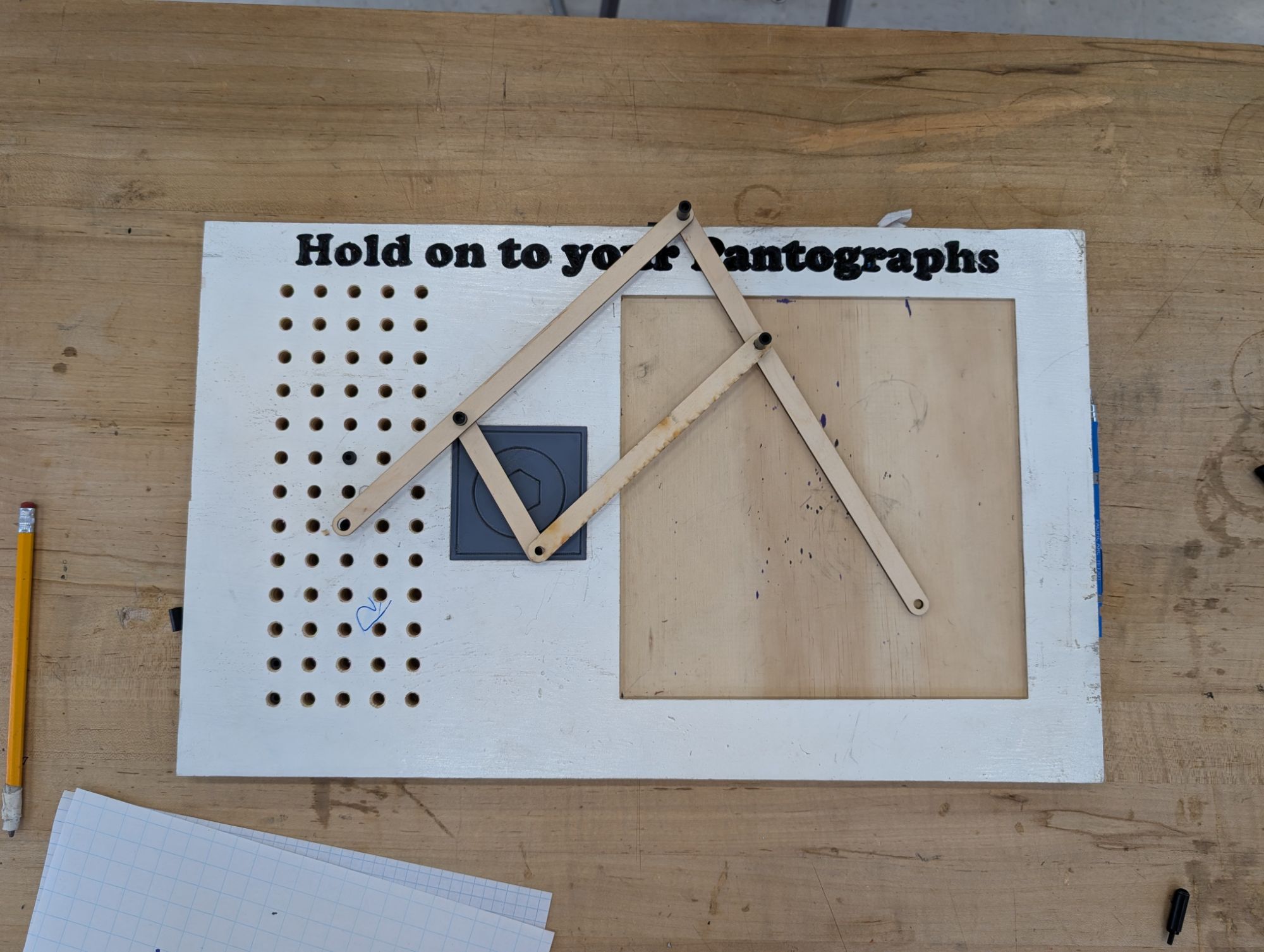
Attaching to the rig: one hand only
This is the biggest rule in the project. Your pantograph is pinned, clamped, or fastened to the rig. Then the only hand on it is the one on the stylus. Not your other hand on the pivot, not your partner holding the board. The machine makes the 3× copy all by itself.
If you have to hold something down to make it work, the pantograph isn't done yet.
- One pivot, held still. It can turn, but it can't slide, lift, or rock. The pivot is the one point that never moves.
- A bushing in a pivot hole is one way. The holes are made to grip a 7 mm nylon bushing. Link 1 turns on the outside of it.
- Your own pin or peg works too, like a printed peg sized to press into a hole. Fit-test it first. The board's holes are sized for 7 mm, not for whatever your printer makes.
- A clamp works if your pivot still lands where your pivot math says.
- No changes to the board. No glue, no tape, no new holes. It comes off clean so the next team can use the rig.
- Keep link 1 from riding up. When you push the stylus, link 1 wants to lift off the pivot. A cap, a collar, or a screw and washer on top stops it.
Fasten it to the board and take your hands off. Then put one hand on the stylus and trace the whole insert. Nothing lifts, slides, or rocks at the pivot, and nobody touches anything else. If it fails, fix the attachment before you fix anything else. Play at the pivot shows up 2× in the copy.
The two ends: your stylus and your pencil
Most teams spend their time on the links and leave these two for the end. Then they tape a pencil on and use a loose screw as a stylus, and the copy comes out wavy. These are the only two parts that touch the drawing. Plan them in your first sketches, model them in Onshape, and test them like any other part.
stylus × 3 pivot × 2 pencil × 1
If your stylus can wiggle 0.5 mm in its hole, the copy can be off by 1.5 mm. The same wiggle at the pencil costs only 0.5 mm. Spend your tightest fit on the stylus.
The tracing insert and your stylus
On test day you don't trace a drawing on paper. A 3D-printed insert drops into the Trace Here box. Its shapes are grooves cut into the plastic. Your pantograph needs a stylus: a point at T that rides in a groove, so you can push it around each shape.
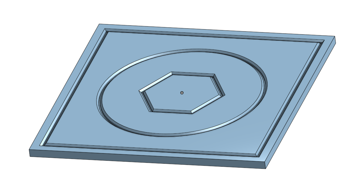
- One hand on the stylus. That's the only hand on the pantograph. You hold the stylus, push it around the groove, and the rest of the machine follows. Nobody touches the pencil.
- It's also a joint. Two links meet at T, so the stylus is the pin they both turn on. Treat it like your best joint: measured, fit-tested, and the tightest clearance you can get without binding. Play here shows up 3× in the copy.
- Make it something you can hold. A handle that stands up above the links, fat enough to pinch, so your fingers grip it without bumping a link.
- Hold it low. Push near the links, not at the top. The higher you push, the more a stylus tilts, and a tilted stylus puts the tip somewhere other than under T.
- Keep it straight up. A thin link gives the stylus only 1/8 in of wood to lean on. A longer sleeve, a printed boss, or a collar above and below the links stops it leaning.
- Fit the tip to the groove. Measure the groove's width and depth with calipers. The tip needs a clearance fit: loose enough to slide, snug enough not to wander side to side. Any play between tip and groove shows up 3× bigger in the copy.
- Mind the corners. A fat tip rounds off the hexagon's corners. A thinner or pointed tip follows them.
- Set the height. The tip rests in the groove, and the links ride above the insert without dragging. The stylus length decides that gap.
- What it's made of is up to you. A bolt with a rounded tip, a standoff, a dowel, or a printed peg could all work. It just has to sit exactly at T and not wiggle.

The pencil holder
Nobody touches the pencil, so the holder does three jobs on its own: keep the point exactly at D, keep it straight up, and keep it pressed on the paper.
- Point exactly at D. The center of the pencil is the drawing point. In your sketch, D is the center of the holder's hole, on the line from O through T.
- Straight up. A leaning pencil draws to one side of D, and the lean changes as the links move. A tall sleeve (a printed tube or a few stacked layers of wood) keeps it straight.
- Pressure with no hand. The easiest way is gravity. Let the pencil slide up and down in a clearance-fit sleeve, so its own weight holds the point on the paper. Add weight on top if it skips. A rubber band or a spring works too.
- Not too much. Too much pressure drags, the links bend, and the stylus gets hard to push. Too little and it skips. Test both.
- Sliding or fixed. A pencil clamped tight can lift off the paper wherever the board isn't flat. A sliding pencil follows the paper, but any side play in its sleeve shows up in the copy. Keep that play small.
- A thin line. A sharp point or a mechanical-pencil lead draws a thin line, and a thin line is easier to measure for your accuracy report.
- Easy to swap. You'll sharpen or change the pencil. Don't make it something you have to take apart.
- Measure your pencil. Pencils aren't all the same size. Size the sleeve from the one you'll use on test day.

How a pantograph makes it 3×
This example is 2×, not 3×. It's a pantograph that doubles, so you can see how it works without being handed your answer. Four links, six holes. O is the pivot on the board. T is the tracer. D is the pencil.
OB = OA ÷ k BT = AD ÷ k
Then finish the parallelogram: AC = BT and TC = BA. If you did, then OD = k × OT in every position. The example uses k = 2. Yours is 3.
Why it works
Triangle O-B-T and triangle O-A-D have the same shape. The parallelogram keeps BT parallel to AD, and OB is 1/k of OA. So every side of the small triangle is 1/k of the big one, and they share the corner at O. Same shape, same corner, so T sits on the line from O to D, 1/k of the way out. Move the tracer anywhere, and the pencil makes the same move, k times bigger.
It's not the only layout
- The arms don't have to be equal. OA and AD can be different lengths. The rule still works.
- The tracer or pencil can sit on a longer link instead of at a joint, as long as it's still on the line from O.
- Swap the tracer and pencil and it shrinks. Put the pencil at T and the tracer at D, and you get a copy 3× smaller. That's what last year's did.
- Every layout gets the same test: O, T and D on one line, and OD = 3 × OT. Show it with your own link lengths.
Check it in Onshape before you cut
- Sketch the links as lines, with a point at every hole. Fix point O.
- Constrain the parallelogram: BT parallel to AC, TC parallel to BA.
- Dimension with variables: for example
#OAand#AD, and#OA / 3for OB. - Drag T around. D should follow. Measure OT and OD in three different positions. OD ÷ OT should be 3 every time.
Picking your pivot hole
Where you put the pivot decides where the copy lands. The copy is always 3× as far from the pivot as the original, along the same line. Pick the wrong hole and your copy runs off the edge of Draw Here, even if the scale is perfect.
Work it out on the centerline. Say the pivot is x inches left of the center of Trace Here. The center of the copy lands 3x from the pivot. For it to land in the center of Draw Here, the gap between the two box centers, 6.75 in, has to equal 3x − x.
copy moves 2 × as far as the pivot, the opposite way
A pivot 0.3 in too far right puts the copy 0.6 in too far left. Same rule up and down: one row off the middle moves the copy almost 2 in.
- Measure how far holes 3 and 4 are from the ideal point on the real board.
- Work out where your copy lands from each. Then pick the hole that keeps the whole copy inside Draw Here.
- Write it in your notebook: the hole, the distance, and where the copy's center lands.
Reach: can the pencil get everywhere?
- The far corner. The far corners of Draw Here are about 15 to 16 in from holes 3 and 4. The pencil has to get there without the elbow at A going perfectly straight. A straight elbow locks up.
- The near edge. The near edge of Trace Here is only about 1.5 to 2.2 in from holes 3 and 4. The tracer has to reach it without the arms folding flat onto each other.
- The limit. No link longer than 18 in. Check your arm lengths against both ends before you commit.
- Try it in your sketch. Drag T to all four corners of Trace Here. If D can't follow, your arms are too short or too long.
Picking your joints
How you join the links is your call. There's no single right answer, but every method has a catch, and every part you can buy or make comes out a little different each time. Compare at least two methods, pick one, and write down why.
| Method | Links turn on | Watch out for | What varies |
|---|---|---|---|
| M3 bolt and nut | The bolt's threads | Threads chew the wood hole bigger over time. A plain nut works loose as the joint turns. | Thread size, and the laser-cut hole |
| M3 bolt through a nylon bushing | The outside of the bushing | The bushing has to be a bit longer than the wood stack. Only the lengths in the bag. | Bushing outside size and length, bag to bag |
| 3D-printed bushing, top and bottom | The printed sleeve | The halves have to press together and stay. Printed holes come out small, pegs come out big. | Every print. Check the tolerance blocks at each printer for clearance numbers. |
| Your own idea | You decide | Run it by Mr. Hubbard before you build it. | Measure it and find out |
- Try two before you pick. Build one joint each way on scrap and turn it. Which one wiggles least? Which stays together?
- Pick, test, accept. No method is perfect. Pick one, measure how much it varies, and design for that. Then write down how much play you're living with and what it does to the copy.
- Write down why. "We picked printed bushings because the bolts wore the holes out" is a reason. "They looked cool" isn't.
Measure first
Every hole you draw is sized from a real part. Don't trust the number on the bag, or the number in your Onshape model for a printed part. Measure with calipers, measure 5 of each, and write them all in your notebook.
| Part | The spec says | Why you need it |
|---|---|---|
| M3 bolt, thread Ø | 3 mm | The hole, if links turn on the bolt. Or the bushing's inside, if it passes through one. |
| Nylon bushing, outside Ø | 7 mm | If you use them: every hole a link turns on, and the board's pivot holes |
| Nylon bushing, inside Ø | 3 mm | The M3 bolt goes through it |
| Nylon bushing, length | 3, 5, 8, 13 or 20 mm | Has to match the stack of links at each joint |
| Printed bushing or pin | Whatever you modeled | Measure what came off the printer, not your model |
| Plywood thickness | 1/8 in (3.2 mm) | "1/8 in" plywood is often thinner. Last year's sheet was 0.11 in. |
| Pencil or lead Ø | Measure it | The pencil holder |
| Insert groove, width and depth | Measure it | Your stylus tip |

Do the math on the width. A link can be 1/2 in (12.7 mm) wide. A 7 mm hole leaves less than 3 mm of wood on each side. Keep holes away from the ends, and give the wood around them a rounded end.
Every part varies
The laser cutter is accurate, but not perfect. Store-bought bolts and bushings aren't all exactly the same size. Printed parts vary even more. You can't make that go away. What you can do is measure it, design for it, and know what it does to your copy.
- Measure 5, not 1. Five of each joint part you'll use, with calipers, in the same spot on each.
- Write down the smallest, the biggest, and the average.
- Size the hole for the biggest. A clearance hole has to fit every part in the bag, not just the one in your hand. Find it on your fit strip.
- Check the play with the smallest. That's the most wiggle you'll get. Write it down.
- Decide if you can live with it. Put your best-fitting parts where play hurts most: the stylus first, then the pivot.
| Part | 1 | 2 | 3 | 4 | 5 | Smallest | Biggest | Average |
|---|---|---|---|---|---|---|---|---|
| Bushing, outside Ø (mm) | 6.96 | 7.02 | 6.93 | 7.05 | 6.99 | 6.93 | 7.05 | 6.99 |
An example, not real measurements. Yours will have a row for every joint part.
worst play = hole size − smallest part
Say the hole that fits the biggest bushing measures 7.10 mm. Worst play is 7.10 − 6.93 = 0.17 mm. At the stylus that's up to 3 × 0.17 = 0.51 mm in the copy. On a 192 mm line, that's under 0.3% error. You can live with that. Do this math for your own parts and put it in your notebook.
Fits: every joint needs one
This is the part of the project that's about tolerance. A pantograph has several joints, and each one needs the right fit. Too tight and it binds. Too loose and the pencil wobbles.
| Joint | Fit | Why |
|---|---|---|
| Link turning on a bolt, bushing, or pin | Clearance | Has to turn freely, with as little play as you can get |
| Links turning on the stylus | Clearance, your tightest | Play here shows up 3× in the copy |
| Link 1 on the pivot | Clearance | Same as any moving joint. Play here shows up 2×. |
| Pivot in the board's hole | Interference (press) | The holes are made to grip a 7 mm nylon bushing. Fit-test anything else. |
| Part that should stay with one link | Interference (press) | Optional. It becomes a pin, and the next link turns on it. Printed bushing halves press together this way. |
| Pencil in its holder | Your call | Clearance if it slides down onto the paper. Tight if it's fixed. See the pencil holder. |
- A bit longer than the stack. Add up the wood at each joint. Whatever the links turn on (a bushing or a printed sleeve) has to be a little longer, so the screw clamps it, not the links. If it's shorter, the screw squeezes the wood and nothing turns.
- Bare bolt and nut? The nut can't be tight, or nothing turns. Set it just loose enough, and keep it there with a lock nut or two nuts tightened against each other.
- Links that cross sit on different layers. Plan which link is on top at every joint, and draw the stack in your notebook.
Backlash: the wobble you can't see until it draws
Backlash is play in a joint: how far one part can move before the other one follows. Every joint with extra clearance adds a little. One loose joint might feel fine in your hand and still draw a wavy line.
The stylus matters most. Play at the stylus shows up 3× in the copy, because the links don't move until the slack is taken up. Next is the pivot: the copy moves 2× as far as the pivot moves (see above). Play at the pencil shows up 1×.
Laser-cut holes aren't the size you draw
The laser burns away a thin line of wood as it cuts. That line is the kerf. Holes come out a little bigger than you drew them, and parts come out a little smaller. How much depends on the laser and the wood, so don't guess. Test it.
- Cut a fit strip first. One scrap strip with a row of holes, each a little bigger than the last (0.1 mm steps work), around your measured part size. Engrave the drawn size next to each hole.
- Try your biggest and smallest parts in every hole. Find the one that turns freely on the biggest with the least wobble on the smallest. That's your clearance hole. Find the one that grips. That's your press-fit hole.
- The laser varies too. Cut your chosen hole size three times, in different spots on the sheet, and try your part in each. If they don't all match, that's more variation to plan for. Cut your real links from the same sheet as your strip when you can.
- Put it in a variable. In Onshape,
#hole= the clearance size from your strip. Size every turning hole with it. If the fit is wrong, you change one number. - Kerf Compensation is one of the Onshape add-ons on Making Parts. If you use it, cut your fit strip with it too, so the strip tests what you'll really cut.

What to research
- How pantographs work and where they're used: copying drawings, engraving, sign making. Write down your sources.
- Backlash, and how machines keep it small. Start with Backlash (engineering).
- Fits: clearance, transition, and interference. Use your notes from class.
- Joint methods: at least two from picking your joints. How do real machines join moving links?
- Tolerance and variation: why no two parts are exactly the same size, and how engineers design for it.
- Percent error: how to work it out. You'll need it for your accuracy report.
- Your parts: every measurement in the table above, 5 of each.
- Last year's pantograph on the overview. What would you keep, and what would you change?
Questions you should consider
- Which hole is your pivot, and where does the center of your copy land?
- How long are your arms? Can the pencil reach the far corners of Draw Here, and the stylus the near edge of Trace Here?
- How does it fasten to the rig, so it works with only one hand on the stylus? Does it pass the let-go test?
- What is your stylus? What tip rides in the groove, how do the two links turn on it, and where does your hand hold it?
- What is your pencil holder? What keeps the point exactly at D, straight up, and on the paper when nobody is allowed to touch it?
- What keeps the links from dragging on the paper and the insert?
- Which joint method did you pick, and why? How much does it vary?
- Which links stack at each joint, and how long does each joint part need to be?
- Where could it wobble, and where could it bind?
Building it in Onshape
- Start from your line sketch. The distance between two holes is the link length from your scale math. The outline around the holes is yours to shape.
- Dimension hole center to hole center, never from the end of a link.
- Use variables:
#OA,#AD,#holefrom your fit strip, and#tfor the wood thickness you measured. - One part per link, named with its version:
link1_v2. - Assemble it with mates and drag it through the trace box before you cut. Look for links that hit each other.
- Lay the parts flat for the laser. See Making Parts for how to submit a file.
Checking your scale
A quick check for every version while you're still building. On test day you'll do the full accuracy report.
- Trace something with a straight line in it. A square or a letter works well.
- Measure the line on the original, in millimeters. More digits make a better check.
- Measure the same line on the copy.
- Divide: copy ÷ original. 3.00 is perfect. 2.85 to 3.15 is within 5%.
- Check two directions, one across and one up and down. If they're different, something is out of line.
76 mm ÷ 25 mm = 3.04 error = 0.04 ÷ 3 = 1.3%
A 25 mm line on the original came out 76 mm on the copy. That's 1.3% too big.
The accuracy report
On test day your pantograph draws the insert's shapes. Then you prove how good the copy is. Measure the original and the copy, work out the percent error, and put the results in your presentation. One measurement can be lucky. Six or more tell the truth.
- Draw the copy on test day: fastened to the rig, one hand on the stylus, nobody touching the pencil.
- Pick at least 6 features to measure. Use every shape, and for each one, measure across and up and down. For example: the square's width and height, the circle across and up and down, the hexagon across its flats and across its corners.
- Measure the original on the insert, with calipers, to the center of the groove. That's the path your stylus tip follows.
- Measure the same features on the copy, center of the pencil line to center of the pencil line, in millimeters.
- Work out the error for each one, then the average and the worst.
- Look for a pattern, and make your best guess at the cause.
expected = 3 × original % error = | copy − expected | ÷ expected × 100
The bars mean "ignore the sign." A copy 2 mm too big and a copy 2 mm too small are both 2 mm off. Then average all your % errors, and pick out the worst one.
| Feature | Original (mm) | Expected 3× (mm) | Copy (mm) | Scale | % error |
|---|---|---|---|---|---|
| Square, across | 64.0 | 192.0 | 193 | 3.02 | 0.5 |
| Square, up and down | 64.0 | 192.0 | 189 | 2.95 | 1.6 |
| Circle, across | 38.0 | 114.0 | 115 | 3.03 | 0.9 |
| Circle, up and down | 38.0 | 114.0 | 112 | 2.95 | 1.8 |
| Hexagon, across flats | 25.0 | 75.0 | 76 | 3.04 | 1.3 |
| Hexagon, across corners | 28.9 | 86.7 | 87 | 3.01 | 0.3 |
| Average | 1.1 | ||||
| Worst | 1.8 |
An example, not the real insert's sizes. Measure yours.
- Average the errors, not the scales. In the example, the scales average out to exactly 3.00, which looks perfect. It isn't. Too big and too small cancel out. The average error, 1.1%, is the honest number.
- Find the pattern. In the example, both up-and-down measurements came out short, and the across ones were fine. Something only goes wrong in one direction. Maybe the pivot rocks that way, or a joint has play in that direction. That's your next fix.
- 5% or less, on average, is the target for the final product score.
Put this in your presentation
- The copy, next to the original, with the features you measured marked.
- Your table: original, expected, copy, and % error for every measurement.
- Your average and worst error.
- The pattern, and your best guess at the cause, using what you know about your joints and their play.

Test and evaluate
Change tracking
One row for every version, in your notebook. Write your guess at the cause before you fix it, even if it turns out wrong. Make one change per version when you can, so you know what made the difference. Give the Onshape parts the same version numbers.
| Version | What failed | Our guess at the cause | What we changed | Scale (% error) |
|---|---|---|---|---|
| v1 | Copy came out too big. | Hole B was placed from the end of link 1, not from hole O. | Re-dimensioned hole center to hole center with #OA / 3. | 3.31 (10.3%) |
| v2 | Lines wavy. Pencil wiggles when the stylus stops. | Too much play where the links turn on the stylus. | Cut those two links with the next hole down on our fit strip. | 3.02 (0.7%) |
| v3 | Pivot lifts when we push the stylus. Needed a second hand on it. | Nothing keeps link 1 from riding up the pivot. | Printed a cap that presses onto the pivot above link 1. | 3.02 (0.7%) |
| v4 | Pencil skips on curves. | Not enough weight on the pencil. | Made the pencil slide in a printed sleeve and added a washer stack on top. | 3.03 (1.0%) |
An example, not a real team's log. Yours will have more rows.
Your notebook and Google Classroom
Your notebook and your Classroom photos are where stages 1–4 of the rubric are scored from, and they're most of what you'll show in your presentation. Do it as you go. You can't photograph a prototype you already took apart.
In your notebook, in order and dated
- The problem. The goal and every rule in your own words, and which rule limits you most.
- Research and measurements. Your sources, and the measurement table filled in.
- Brainstorm sketches. Several layouts, each answering the design questions, with a sketch of the stylus, the pencil holder, and how it fastens to the rig.
- Joints. The methods you compared, which one you picked and why, and your 5-sample measurements with the worst-play math.
- The math. Your scale check, pivot hole, and reach, every step shown. Which layout you picked, and why.
- Fit tests. Your fit strip, and the hole sizes you chose.
- Every version. The change-tracking table, and each test tracing's measured scale.
- The accuracy report. Your test-day measurements, errors, average, and worst.
To the Google Classroom assignment
- Brainstorms: photos of your sketch pages.
- Research: photos of your research and measurement pages.
- Onshape screenshots: your line sketch, your links with the variable table showing, and the assembly.
- Final product: the pantograph fastened to the board, from above, and close-ups of your stylus and pencil holder.
- Accuracy report: your test-day copy with the measured features marked, and your table of errors.
Each of you submits.
The presentation
Your team presents for 4 minutes or less. Everyone in the room already knows the challenge and the brief, so don't explain them. Spend every minute on your solution: what you tried, what you changed, and how accurate it turned out.
Show these four
- Brainstorms: your sketches, which layout and joint method you picked, and why.
- Onshape screenshots: your line sketch, your links with the variables, and the assembly.
- Prototypes: every version, what failed, and what you changed.
- Accuracy report: your test-day copy, your table of measurements and errors, the average and the worst, and what you think caused it. See the accuracy report.
- Both of you present. You're scored on your own, so be ready to explain any part of the pantograph, not just the part you built.
- Your Classroom photos are most of your slides already.
Tuning: problems you will have
The copy is too big or too small. Your hole spacing doesn't match your math. Measure hole center to hole center on the real links. Check OB = OA ÷ 3 and BT = AD ÷ 3.
The copy comes out twisted or lopsided. T isn't on the line from O to D. Check that the opposite sides of your parallelogram are really equal.
Lines are wavy or wobbly. Backlash. Check the stylus first (play there shows up 3×), then the pivot (2×). Use the next tighter hole from your fit strip, or a better-fitting part from your five.
The pivot lifts, slides, or needs a second hand. It isn't fastened well enough. Add a cap or collar so link 1 can't ride up, and check the pivot's fit in the board. Run the let-go test again.
It's stiff or binds. Holes too tight, or a joint part shorter than its stack so the screw is clamping the wood. Go one hole up on your fit strip, or use a longer part. Check the stylus and pencil aren't leaning and dragging.
The pencil skips or draws faint. Not enough pressure on the paper. Let the pencil slide in its hole so its own weight holds it down, or add weight over it.
The copy runs off Draw Here. Wrong pivot hole. Every inch the pivot moves, the copy moves 2 in the other way. Redo the pivot math.
Before you send anything to the laser cutter, read Making Parts in the shop procedures. Wasted wood counts on your daily grading page score.